Roof challenge
Roof is the uppermost portion of a car. It provides covering to the vehicle from top and protects the occupants from rain, snow and sun rays. The roof section is tilted to provide more strength. The following figure shows the roof of a Toyota INNOVA CRYSTA.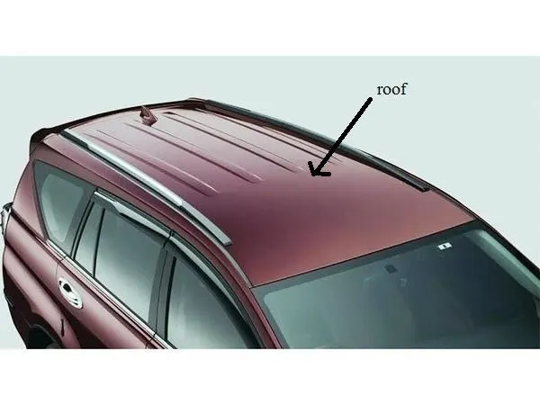
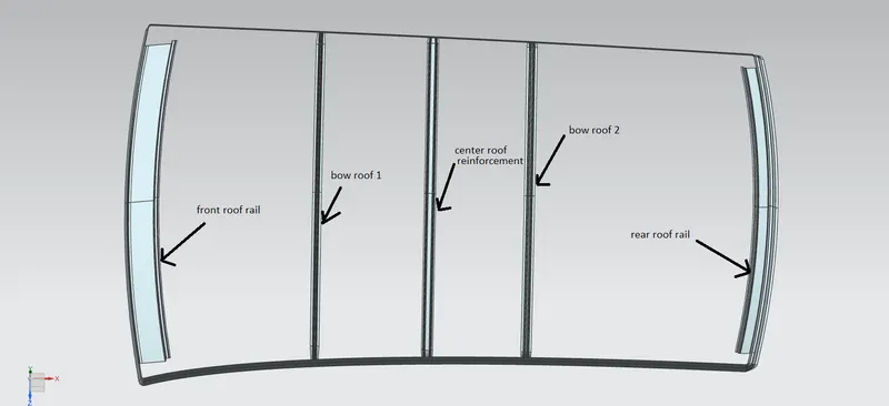
The inner panel of the roof constitutes of front and rear roof rails and also bow roofs and centre roof reinforcement. Front roof rail joins with the windshield and body side outer. Rear roof rail joins with the back door and body side outer. The roof rails are produced in-house by the vehicle OEM.
An opening angle of 3 degrees is provided to the front roof rail for allowing deep drawing. Front roof rail supports brackets for cabin lamp.
A flange width of 21.5 mm is generally given at the front roof rail. Windshield glass is mounted which has thickness of 3.7 to 4.7 mm. A rubber strip of 5 mm is pasted below this and the paste also has a thickness of 5 mm. A molding is also added which has a thickness of 8 mm generally.
A value of 3 degrees opening angle and a flange width of 21.5 mm are generally taken because these values ensures that visibility is maintained from the driver's seat towards the front side of vehicle. Any deviation from these values results in obstruction of view from driver's seat.
A tolerance gap of 2 mm is maintained at the front roof rail for assembly tolerance. This gap becomes more stringent in premium cars.
Bow roof rails are placed where the radius of curvature is not large. A bow roof can be placed either before or after centre roof reinforcement or sometimes two bow roofs can each be placed on either side of centre roof reinforcement depending on the radius of curvature of car roof.
The number of bow roofs increases for longer and taller cars as the roof length will be larger in such cases. The position of roof is validated by means of heat distortion and snow load criteria. These criterias have formulae for calculating certain parameters for validating the position of bow roofs. The parameter calculated has to lie in a certain numerical range in order to meet the criteria.
If the required range is not achieved in the calculations, the roof is sent back to styling team to make changes in roof curvature or the design team itself might incorporate embosses to improve strength in the roof.
Result of challenge:
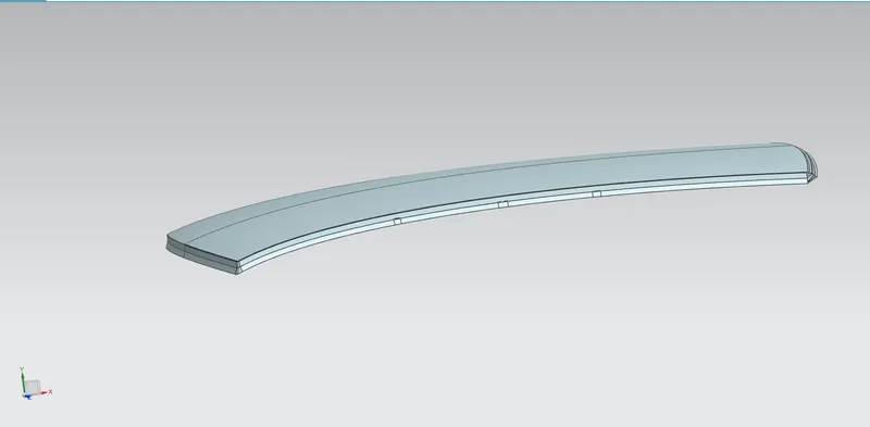
The roof inner panel is designed on the basis of master section provided. The following figure shows the inner panel of roof.
The following figure shows bow roofs, front and rear roof rail and center roof reinforcement.
Inertia analysis is done and the following figures show inertia analysis for the roof sections.
1. Front roof rail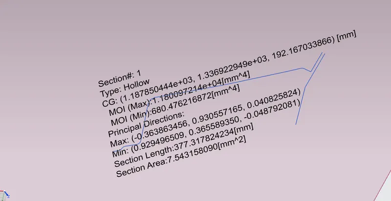
2. Bow roof 1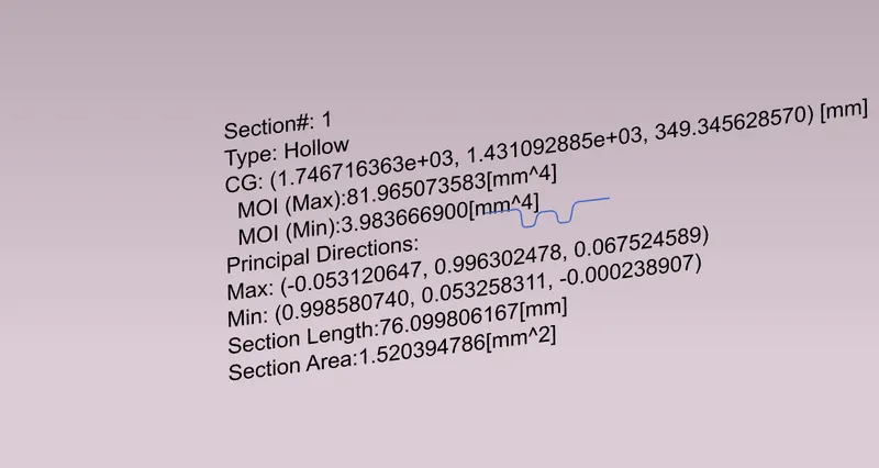
3. Center roof reinforcement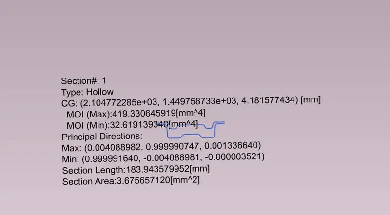
4. Bow roof 2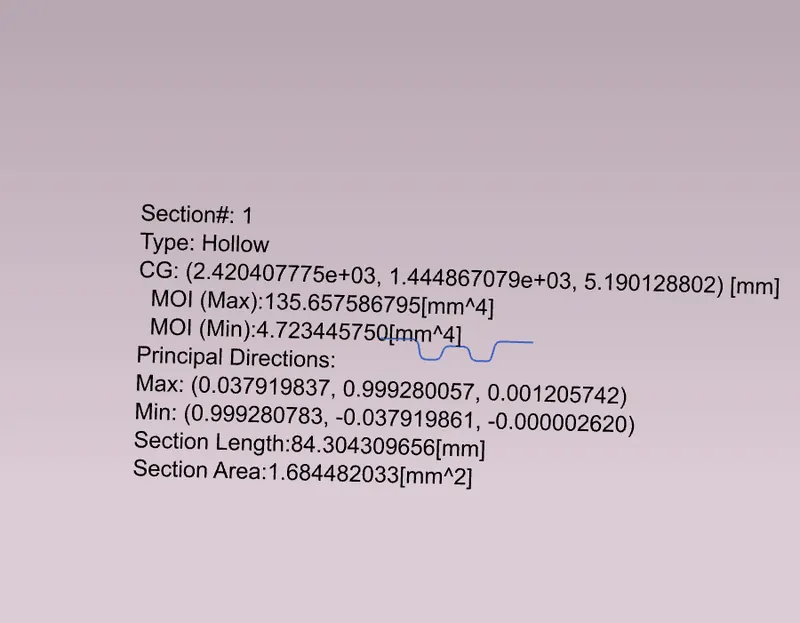
5. Rear roof rail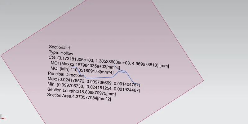
Draft analysis is performed and following figures show draft analysis.
1. Front roof rail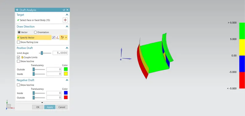
2. Bow roof 1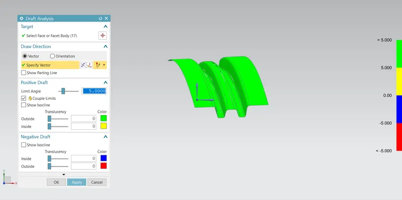
3. Center roof reinforcement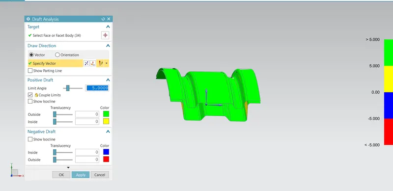
4. Bow roof 2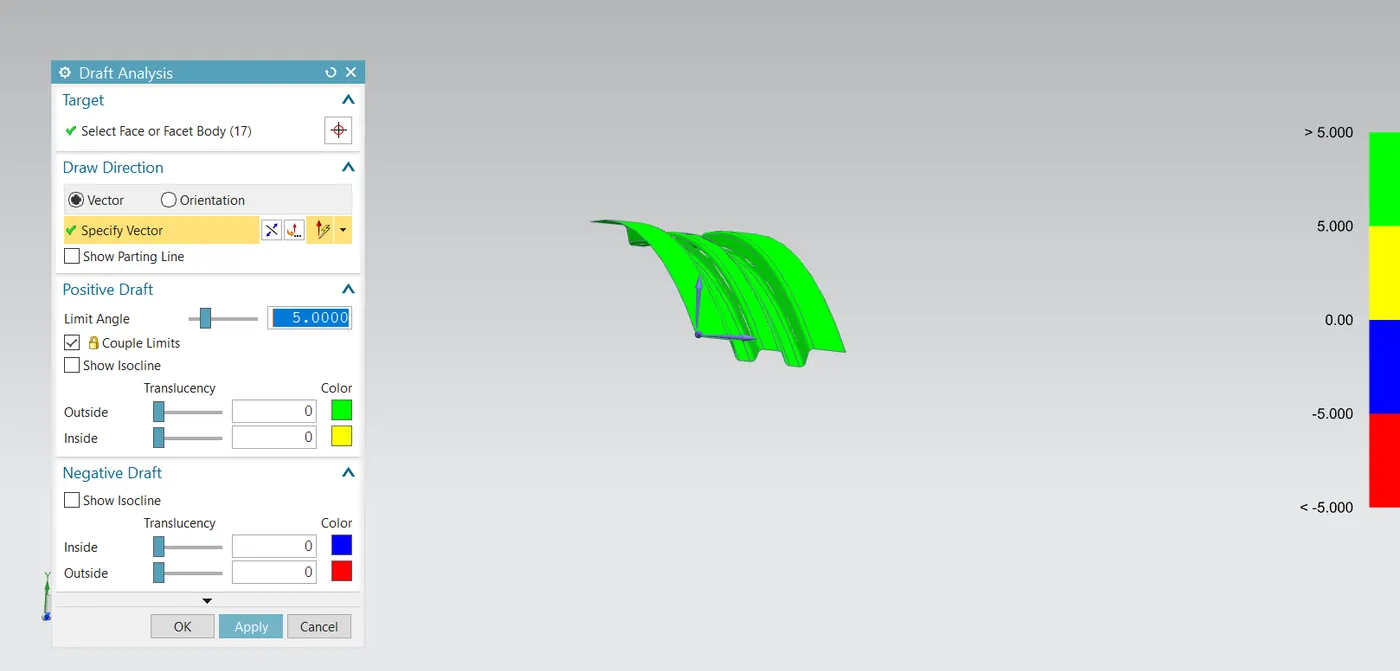
5. Rear roof rail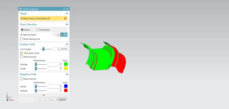
The heat distortion and snow load criteria calculations are performed and the figures below show the calculations.
1. Heat distortion criteria
2. Snow load criteria