Hood design-Week 2
The hood, also known as the bonnet is an opening body panel that covers the engine compartment in a front-engine vehicle. The hood is considered as another type of door in a vehicle as it consists of an outer panel and an inner panel. The inner panel acts as a reinforcement and provides strength to the hood while the outer panel functions as a metal cover. Generally, a gap of 5 mm is provided between the outer and inner panel. A stiffener pad may be present between the outer and inner panel and it does not have a predefined shape. This is added to absorb vibrations coming out from the engine compartment and those emanating due to vehicle motion and thus reduce the NVH levels in a vehicle.
Hood basically can be of two types: In-laid and Wrap-Around Hood.
In an In-laid hood, end point of the side of the car lies on the fender, whereas in a Wrap-Around hood the end point lies on the hood.
The end point is defined using a side refernce line. The side reference line is taken from the ground at an angle of 45 degrees. The point on which the line from the ground at this angle contacts the car surface on the frontal side is taken as the end point. Wrap Around Distance (WAD) is the distance traced along the points on the front structure of car when one end of a flexible tape of reqired length is held at ground reference level and the other end is in contact with the front structure of the car.
When a collision of car occurs with a pedestrain, a Wrap-Around hood ensures that the pedestrian wraps around the hood of the car rather than collapsing onto the ground. The hood has zones for pedestrian safety: Adult WAD impact zone for a WAD of 1500-20000 mm and child WAD impact zone for a WAD of 1000-1500 mm. In these zones, softer sections of the hood are included which is generally achieved by removing material from some sections of hood without imapcting its strength. Material removal results in a softer surface which ensures that the pedestrain doesnot sustain serious inuries due to the impact of getting onto hood surface during a collsion.
An In-laid hood does not ensure that the pedestrian collapses onto the hood during a collsion rather there are more chances of the pedestrain collapsing onto the ground in the event of a collsion.
The hood outer panel is a styling surface and the inner and outer panel are thus never joined together using any welds or rivets since the welds and rivets will be visible outside and thus reduce the aesthetics of the vehicle. Therefore, joining techniques like hemming, gluing and mastics are made use of so as to not compromise with the aesthetics of the vehicle.
Mastic sealants which are in the form of rubber parts and are introduced as a paste between outer and inner panel also tend to decrease NVH levels. They also tend to impart strength in areas around a distance of 80 mm from their centers.
The Hemming process involves bending/ folding the flange of the outer panel over the inner panel in order to achieve a tight fit. Hemming can be carried in two ways: conventional die hemming and roll hemming. In conventional die hemming, the flange is folded over the entire length with a hemming tool. In roll hemming, an industrial robot is used to guide the hemming roller in order to form a flange. Some predetermined steps are taken into consideration while carrying hemming: some amount of gap between outer and inner panel on the side portions of the hood is manintained, a 0.2 mm gap is maintained between outer and inner panel on the top and bottom portions of the hood. These ensure avoidance of any spots on the outer surface of the hood. After hemming is completed, sealants are applied between outer and inner panel to acheive water-tightness.
The following figure shows the hood of a Renault TRIBER.

The opening angle of the hood is decided on the basis of the region where the car is intended to be marketed. For example, for a car to be marketed in India, the hood opening angle is decided on the basis of the average human height in the region, which is generally considered to be 5 feet 5 inches. Using this a proper hood head clearance is determined for deciding the hood opening angle. Thus, a certain angle is decided for a completely open condition of the hood for a vehicle to be marketed in India. In the same manner, if a car is to be marketed in the UK, where the average human height is 6 feet, the hood opening angle will be a bit higher. A suitable hood head clearance is determined for deciding the hood opening angle in its completedly open state to arrive at a certain hood opening angle.
When the hood opening angle is less the hood head clearance becomes less than that intended and there are high chances of a human getting injured due to the hitting of the hood against the head. The opening angle is considered in the initial stage of hood development on the basis of the region where the vehicle is intended to be marketed.
The opening angle of the hood is facilitated by means of a hood balancer. The hood balancer supports or holds the hood safely in its open condition even when external forces such as vibrations or wind are acting and allows the hood to maintain the intended opening angle. The hood balancer is of two types: support rod and gas stay.
The support rod is fixed at one end either on the hood compartment or engine compartment using a hinge joint. A grommet, which is basically a form of clamp is used to house the other end of support rod when the hood is in closed condition. During the hood open condition, the end of support rod which is clamped is attached to a hole slot. This hole slot may sometimes be provided on the hood hinge as well.
The length of the support rod is defined with respect to the hood opening angle. The support rods do not have a linear section since in this condition, the support rod can very easily wobble. Thus, the support rod has curves and bends across its section so as to ensure more rigidity is available in the rod. It is made sure that the support rod does not collide with any components in the engine compartment either when the hood is closed or opened. The gap and packaging constraints are considered to make sure that the support rod does not collide anywhere. The maximum radius of curvature given to bends and curves on the support rod should not be more than 35 mm since there are chances of the rod getting bent due to the weight of the hood when the radius of curvature exceeds more than 35 mm. The support rod is laid on the opposite side of battery to prevent interference with the rod when the hood is opened during the assembly of battery. The support rods generally weigh around 150 to 200 grams.
Following figure shows hood support rod of a Maruti Suzuki WAGON-R.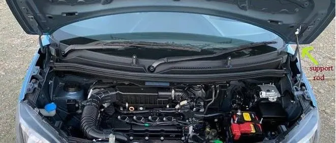
In the gas-stay system, the hood is opened and closed by means of a pneumatically controlled piston rod. In this, one end of the rod is mounted on the hood and the other in the engine compartment. The length of the gas stay is defined by (A-B) + 110 mm >/= B, where A is the length of the piston rod in its fully extended condition and B is the length of the piston rod in its fully retracted condition. Ball studs are used on the hood and engine compartment to fix the two ends of the piston rod. Brackets are used as a reinforcement to install the studs to improve the strength at those points. This is because the gas stay adds additional weight to the hood assembly. The gas stay weighs around 500 to 800 grams.
Following figure shows hood gas-stay of a Hyundai ELANTRA.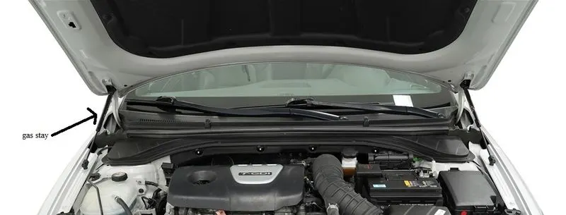
Whenever the hood is opened there should be clearance between the tip or the end point of the hood and striker. A striker is a component that attaches and locks the hood to the engine compartment when the hood is to be closed. For locking and unlocking the hood to the engine compartment a secondary latch is present on the engine compartment which needs to be activated. To activate the secondary latch, a primary motion has to be enabled which is done with the help of a lever present in the vehicle cabin generally located underneath the driver's seat. When this lever is actuated, the hood opens slightly and some space is created to reach out to the primary latch to unlock the hood from the engine compartment. This space is usually 10 to 15 mm across all regions in the global market since a human's finger length can not be defined for such cases.
Some reinforcement is added onto the area where the striker is added on the hood compartment to impart strength as this area tends to become weak due to the installation of the striker. Generally, the thickness of reinforcement added is 1 mm.
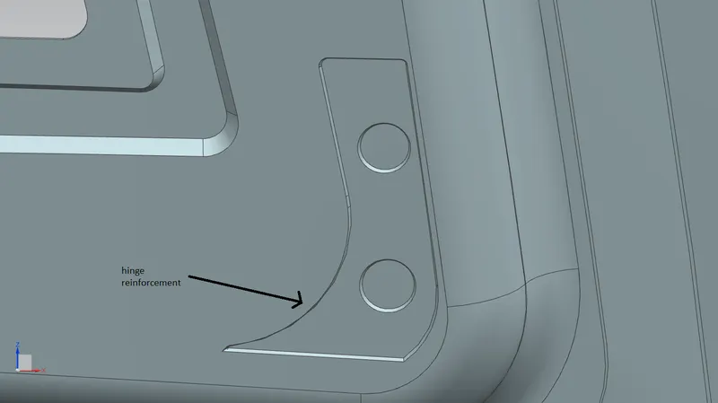
Hinges are present on the hood to enable the opening and closing movement of the hood. The areas where the hinges are located are also reinforced to increase strength there as this tends to decrease due to the installation of hinges.
The location of the hinge and striker are decided tentatively based on the cutlines on hood. The location of the striker is validated. A point on the hinge connecting both hinges along the axis connecting them is marked and centreline of striker is marked. A circle is projected with centre as a point on one of the two hinges lying along axis connecting both hinges and with centrepoint of striker as the radius point. It is then checked that the striker is tangential to the circle trajectory locally. If it is not tangent then the hinge positions are varied to change the centre of circle to ensure that the point on hinge connecting striker is tangential to the circumference.
Maintaining the tangent is important since this ensures that the latch in the engine compartment is positioned with respect to the trajectory as closing between between striker and latch will not take place if tangency isn't maintained. The trajectory is also the trajectory of hood opening and closing.
Result of the challenge:
The master section has been followed while designing the hood inner panel. Embosses have been provided on the hood inner panel alongwith the mastic zones and some surface has been trimmed off around the emboss and mastic zones to reduce the weight as shown in figure below.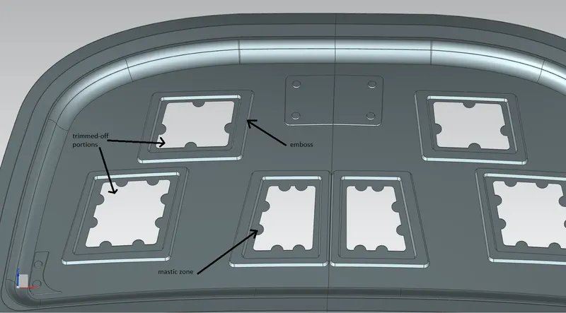
The striker and hinges were first located tentatively and their postions were validated to check for tangency between the trajectory circle and striker at the striker area locally as shown in following figure.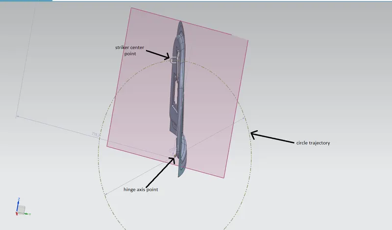
Reinforcement according to the values given in the data have been provided on the striker and hinge locations to ensure strength is imparted to offset any loss of strength which can happen in those areas due to riveting once the striker and hinges are affixed on the hood. The following figures show reinforcements for the striker and hinges. 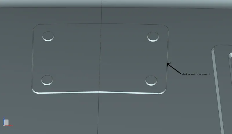
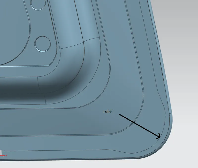
Hemming has been provided between outer and inner panel and relief has been given on the hemming flange on the front and rear section of hood according to the given value. Following figures shows hemming flange and the relief on the flange.
Front relief-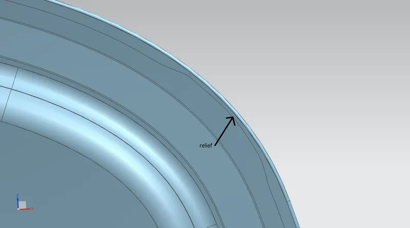
Rear relief-
A thickness of 0.75 mm has been provided on the inner panel and outer panel.