Roof challenge
ROOF DESIGN
AIM
To design the Automotive Roof based on the given styling surface and to analyze the prepared model to check the manufacturability and the feasibility of the design.
ROOF INTRODUCTION
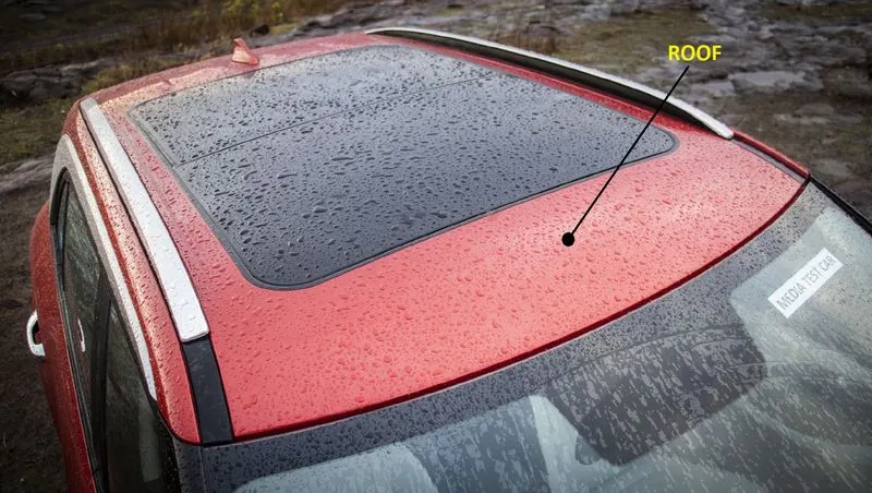
The Roof of a car is the component which encloses the passenger compartment from the top. It protects the Passengers and the interior of the car from external environments thus providing a safe and isolated cabin. The roof plays an important role in the safety, especially in the case of roll-over accidents. To achieve better safety results the roof is designed with reinforcement structures such as rails. All these components are designed to satisfy the basic functions of the roof.
First thing to consider while designing the roof is the opening angle, of the flanges such that there is no negative draft. If the roof rail is flat it is weak and if it is tilted or curved then it has more strength. As the roof is large so to increase the strength of the roof where it appears flat due to its long distance Roof Bow are given to increase the strength of the roof. Since the roof has numerous functions so the roof has to be stronger enough to withstand the damage experienced by it. To have good strength and stiffness, the Roof consists of components. The safety requirements and to improve the performance of the vehicle by weight optimization.
Design consideration:
- Visibility criteria
- Head clearance
- Curvature study
- Heat distortion and snow load criteria
- Material thickness
The major components of the Roof are,
- Outer panel
- Front roof rail
- Rear roof rail
- Bow roofs
- Central roof rail
Material thickness following,
- Outer Panel - 0.75 mm
- Bow roof & Centre Roof - 0.75 mm
- Front & Rear Roof - 0.75 mm
OUTER PANEL
The outer panel is the A-class surface of the roof which encloses the top of the passenger compartment. It is designed to match the input styling surface, thus getting better aerodynamic performance as intended. It also has a significant role in the aesthetics of the vehicle. The outer panel is mounted to the roof rails with the help of mastics and the ditch areas are mounted with spot welds. The commonly used materials for the outer panel are Steel and Aluminum alloys.
Developing the ditch area - Flanges are created on four sides of the roof as per the above-mentioned requirements. The front end flange is given with a width of 21.50 mm to provide adequate space for the rubber sealing, mounting of windshield glass, etc. The rear ditch area is created to allocate the hinges of the backdoor and to allow the swinging of the backdoor to the required opening angle. Some embosses are also provided on the rear to increase the strength locally.
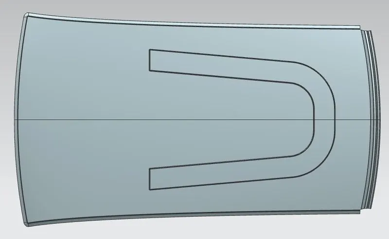
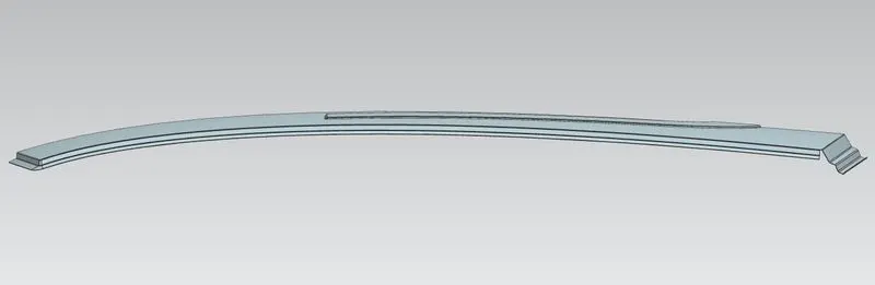
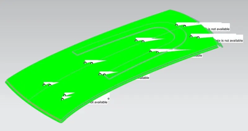
Draft analysis of outer roof was done to check for proper draft angle.
FRONT ROOF RAIL
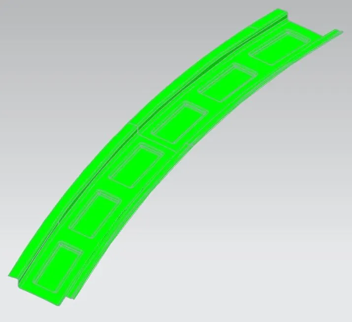
Front roof rails are used in the assembly of a roof in which it provides mounting provisions to windshield glasses and the changes in the front roof rail influences the frontal visibility of the passenger. The major design factor considered is the headroom clearance. The front roof rail also provides provisions for mounting the inside rearview mirror.
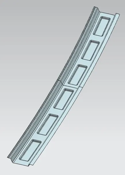
Draft analysis of front roof rail was done to check for proper draft angle.
REAR ROOF RAIL
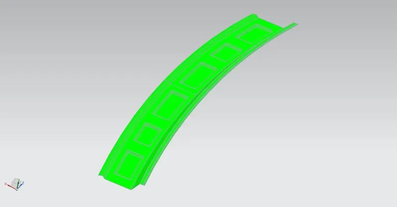
The rear roof rail is similar to the front rail. It is designed to support the back end of the roof and the hinge of the backdoor is also mounted on it.
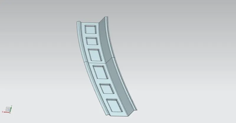
Draft analysis of rear roof rail was done to check for proper draft angle.
BOW ROOFS
The Bow roofs are given to improve the torsional stiffness and load-bearing capacity of the roof structure. The number of bow roofs provided will depend upon the overall dimensions of the roof. They are attached to the outer panel using mastic sealants. Each mastic point will have up to 80 mm circular effective area. The positioning of bow roofs is done based on curvature study. The heat distortion criteria and snow load criteria are checked to analyze the position of the bows in various conditions
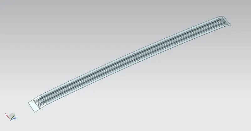
Draft analysis of bow roof 1&2 was done to check for proper draft angle.
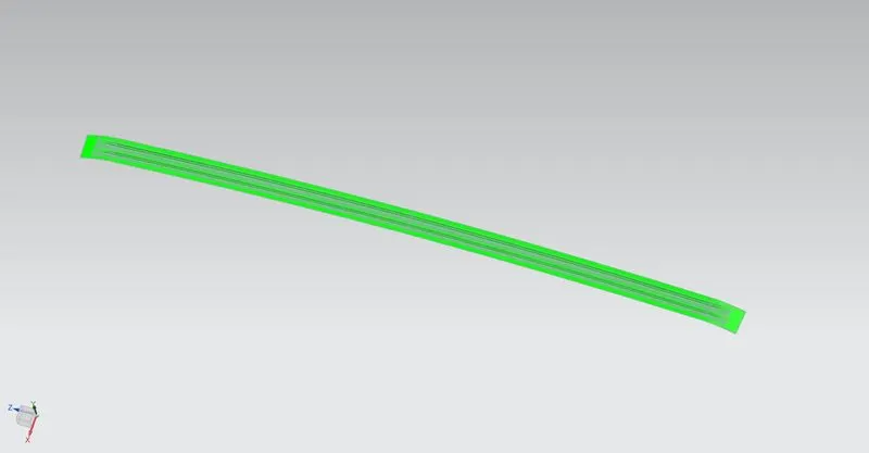
CENTRAL ROOF RAIL
The reinforcement roof at the center is the supporting member at the middle which is mounted to the B pillars on either side. They are attached to the outer panel using mastic sealants. Sometimes it acts as bow roof and sometimes bow roofs are also provided with the reinforcement roof center. In some vehicles a room lamp mounting provision is also given on this part.
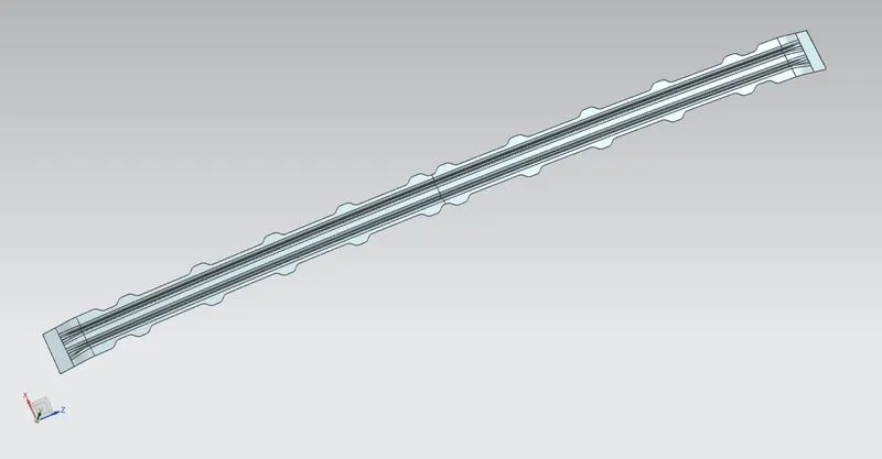
Draft analysis of centre roof was done to check for proper draft angle.
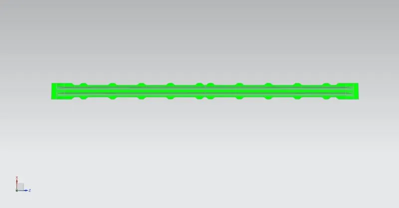
CALCULATION PART
- Heat distortion criteria
- Snow load criteria
HEAT DISTORTION CRITERIA
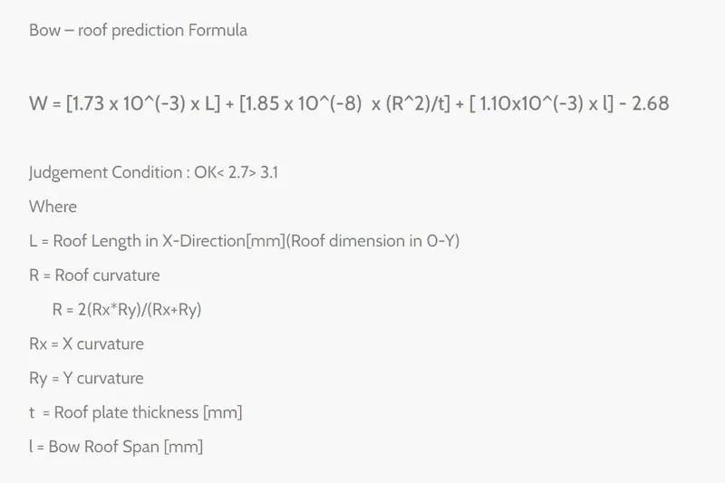
L = 2044mm
t = 0.75mm
RESULT: All values are satisfied
| Rx | Ry | R | I | W | |
| CASE 1 | 2167.74 | 5726.70 | 3145 | 306.8 | 1.44 |
| CASE 2 | 5989.74 | 5023.75 | 5464.38 | 568 | 2.21 |
| CASE 3 | 11128.37 | 3855.70 | 5727.10 | 560 | 2.27 |
| CASE 4 | 15369.70 | 3163.52 | 5247 | 249 | 1.81 |
SNOW LOAD CRITERIA
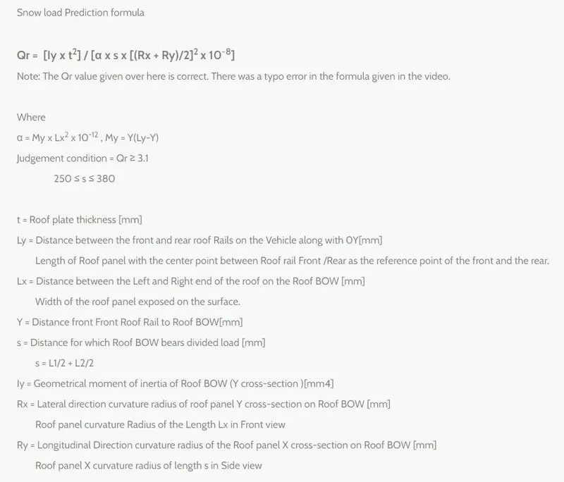
Ly = 2044
t = .75
RESULT: Not satisfied
| Rx | Ry | L1 | L2 | s | Lx | My | Y | α `alpha` | Iy | Qr | |
| CASE 1 | 2261.84 | 4790.72 | 381.3 | 619.3 | 500.3 | 1147.1 | 532972.96 | 381.3 | 0.701 | 242.153 | 5.56 |
| CASE 2 | 5892.90 | 3757.29 | 619.3 | 605 | 612.15 | 1088.8 | 838368 | 619.3 | 0.99 | 335.43 | 2.38 |
| CASE 3 | 11868.32 | 4321.38 | 605 | 352.8 | 478.9 | 1055.5 | 831040 | 605 | 0.925 | 245 | 0.845 |
| CASE 4 | 17516.11 | 3798.54 | 352.8 | 176.4 | 1042.2 | 446955 | 352.8 | 0.4855 |
SECTION INERTIA ANALYSIS
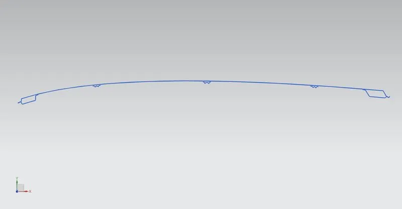
CASE 1
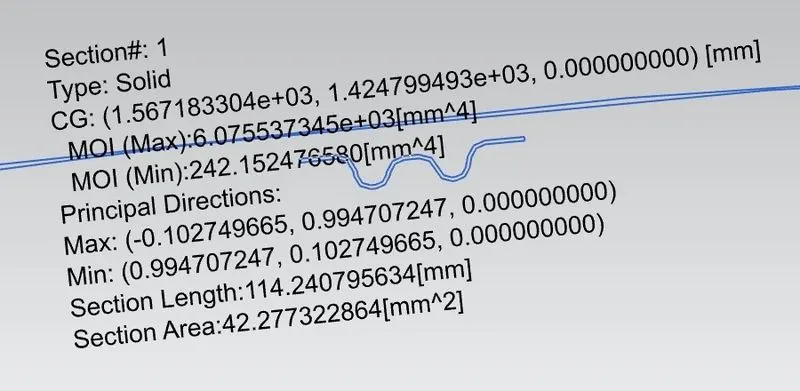
CASE 2
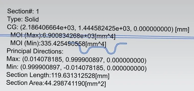
CASE 3
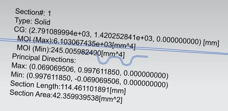
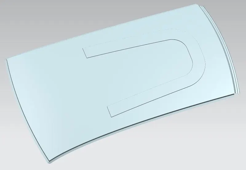
Hence we introduce Emboss on the roof panel. The longer emboss covers the rear portion of the roof to provide more strength.
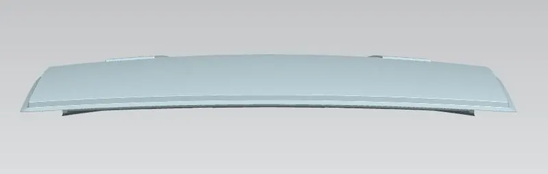
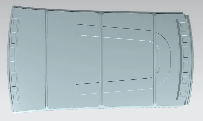
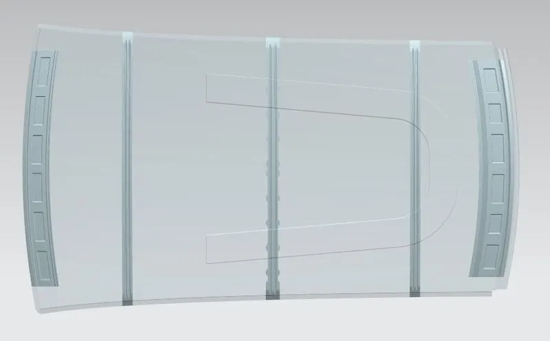
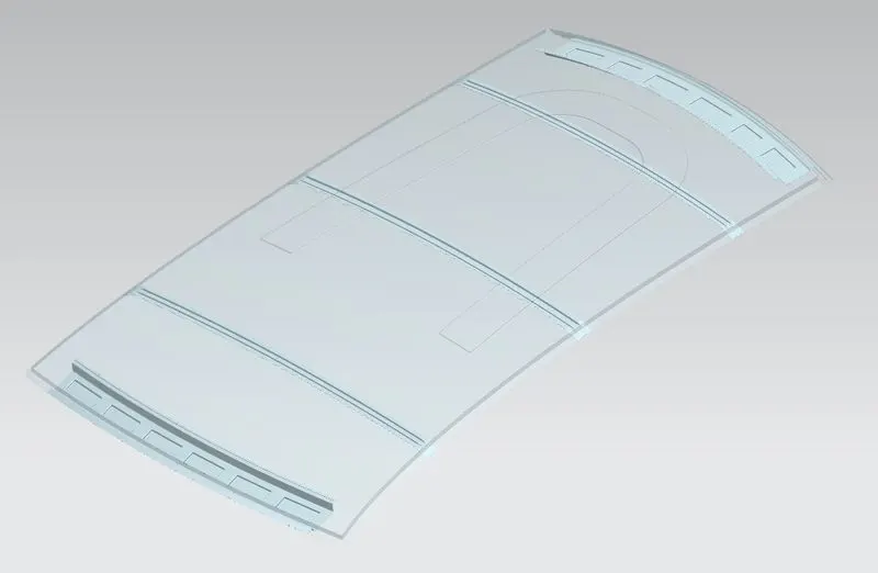
FINAL ROOF MODEL OUTPUT

RESULT
The Roof assembly is designed based on the given styling surface, considering all the geometric, manufacturing, and functional requirements.