Advanced Sheet Metal Design Using NX Cad Challenge_1_Casing Design
CASING DESIGN
OBJECTIVE:
To design a ‘Sheetmetal Casing’ using Siemens NX Sheetmetal application.
INTRODUCTION:
Sheet metal is one of the more versatile materials in the manufacturing industry. The ranges in thickness from 0.5mm to 6mm. And sheet metal casing is an enclosure, normally used for keeping the machine parts protected. Using Siemens NX Sheet metal application features are using by Tab, Bend, Flanges, Holes and Flat pattern.
DESIGN METHODOLOGY:
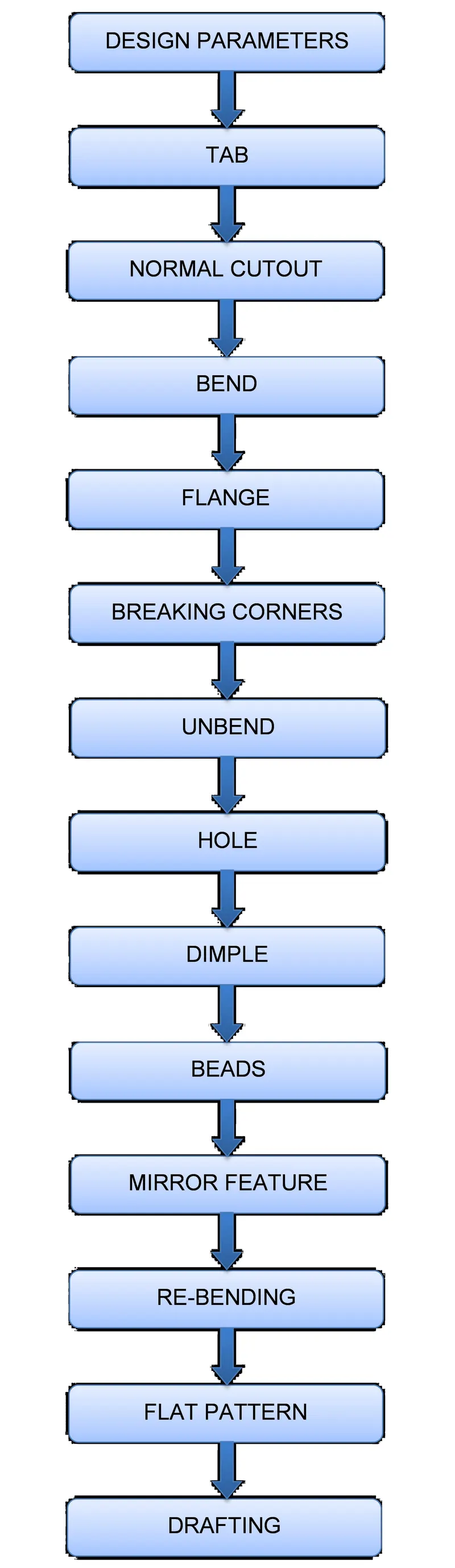
DESCRIPTION:
DESIGN PARAMETERS
To provide the required Material thickness, Bend radius, Relief depth & width, enter the sheetmetal preferences. Set all the global parameters to 1mm.
TAB
To create a base feature command by extruding a sketch along a vector by a thickness value.
NORMAL CUTOUT
Use the normal cutout command to be used cut the material in required shape to sketch the appropriate plane/face.
BEND
To modify the model by bending material on one side of a sketch line, adding the bend between two sides.
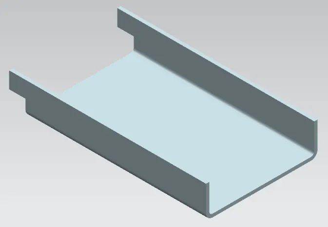
FLANGE
To create a single flange instance or multiple instances by selecting a single or multiple base edges.
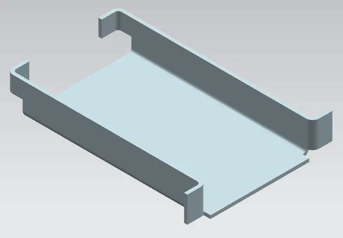
BREAKING CORNERS
Use the break corner command to be used avoids the sharp corners/edges.
UNBEND
Unbend commend to be used flatten the material for create holes, cutout shapes in unbend material.
HOLE
To adding a hole in required places, by using Hole feature command.
DIMPLE
To lift an area of the model inside a sketch that simulates a stamping tool. You can create an indentation in a sheet metal part using a sketched section as the dimple outline.
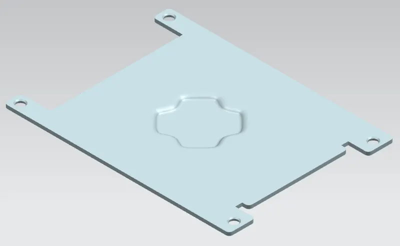
BEADS
Use the Bead command to lift material along the contour of a sketch that simulates a stamping tool. Beads can also be created to stiffen sheet metal parts. And also create beads on deform features in sheet metal parts.
MIRROR FEATURE
Use the mirror feature command used to copies a feature and mirrors it across a plane.
RE-BENDING
Use the Re-bend command to return an unbend feature to its previous bend state. Any features added after the unbend operation are properly repositioned during the re-bend operation.
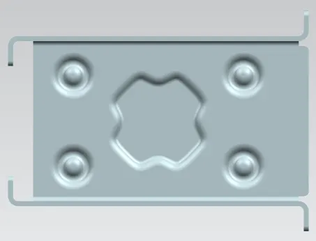
FLAT PATTERN
Flat Pattern tool is used to automatically create a flattened version of a sheet metal part and prepare the model for manufacture. The Flat Pattern feature remains the last feature in the Model tree and maintains the flat model view.
DRAFTING
Which provides tools to create and maintain drawings of the design pattern.
MODEL VIEWS:
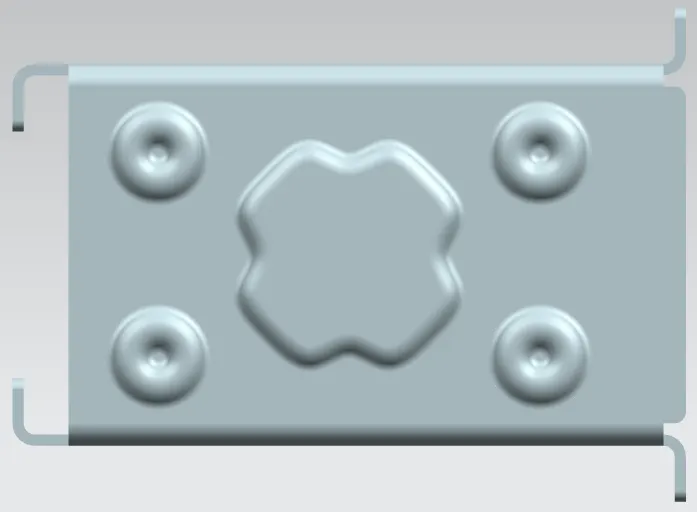
FRONT VIEW
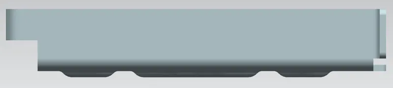
SIDE VIEW
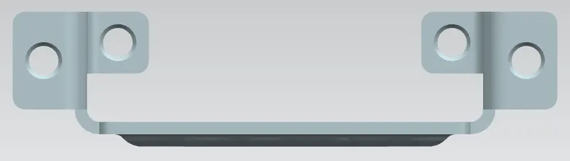
TOP VIEW
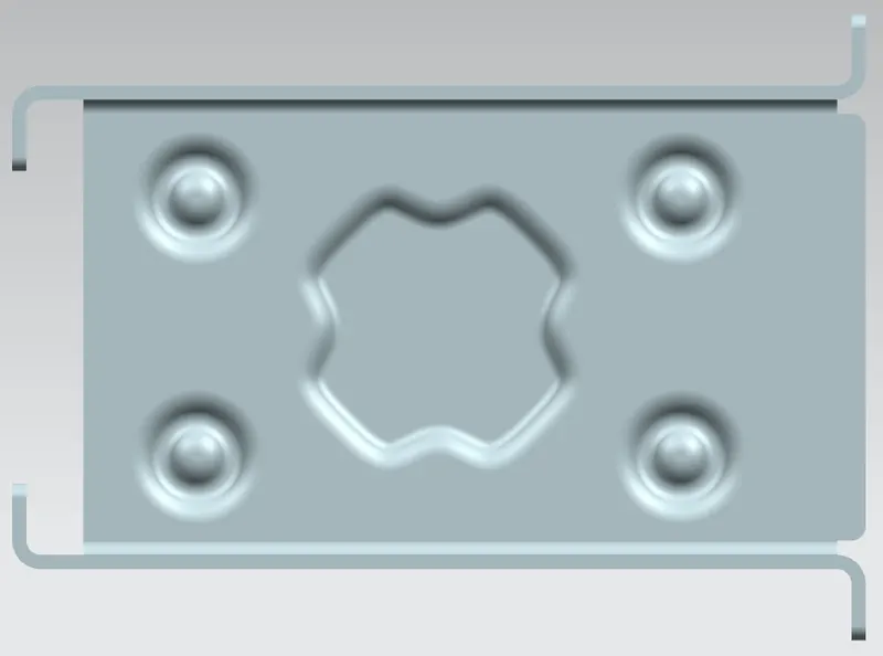
BOTTOM VIEW
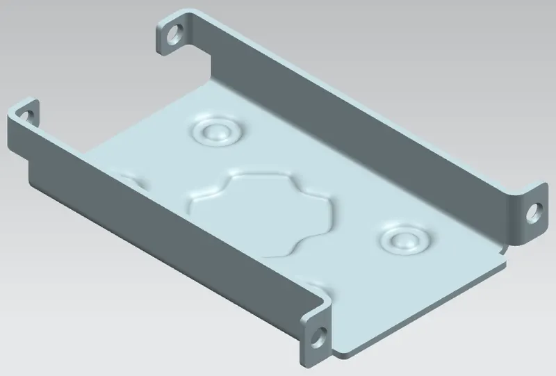
ISOMETRIC VIEW
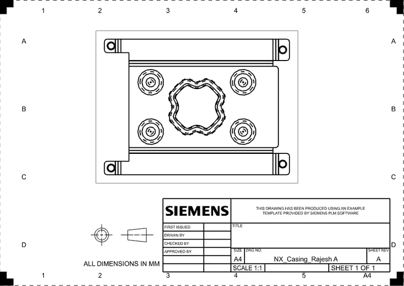
DETAILED DRAWING:
CONCLUSION:
In this Casing design, I have used to design, basic commands of Siemens NX Sheet metal application like Tab, Bend, Flanges, Holes and Flat pattern.