Advanced Sheet Metal Design Using NX Cad Challenge_7_ Metal bracket-II
METAL BRACKET II
OBJECTIVE:
To design a ‘Sheetmetal Metal Bracket’ using Siemens NX Sheetmetal application.
INTRODUCTION:
Sheet metal is one of the more versatile materials in the manufacturing industry. The sheet metal ranges in thickness from 0.5mm to 6mm. And sheet metal casing is an enclosure, normally used for keeping the machine parts protected. Using Siemens NX Sheet metal application features are using by Tab, Bend, Flanges, Holes and Flat pattern.
DESIGN METHODOLOGY:
- Sketch IN YZ PLANE (RIGHT VIEW)
- Sketch IN XZ PLANE (FRONT VIEW)
- CONTOUR FLANGE
- NORMAL CUTOUT
- BREAK CORNER
- NORMAL CUTOUT
- BREAK CORNER
- UNBEND
- NORMAL CUTOUT
- REBEND
- BREAK CORNER
- ADVANCED FLANGE
- UNBEND
- SIMPLE HOLE
- NORMAL CUTOUT
- ADVANCE FLANGE
- REBEND
- GUSSET
- DRAFTING
- FINAL PRODUCT
DESCRIPTION:
CONTOUR FLANGE
To create a flange by extruding a sketch along a vector, or by sweeping a sketch along an edge or chain of edges. NX adds bends automatically using the default bend radius value. To use a different bend radius value, draw arcs in the section, or change the default bend radius value.
NORMAL CUTOUT
To cut material by projecting a sketch onto the model and then cutting perpendicular to the faces intersected by the projection.
BREAK CORNER
To create a round or chamfer sharp corners of a tab or flange.
UNBEND
Unbend commend to be used flatten the material for create holes, cutout shapes in unbend material.
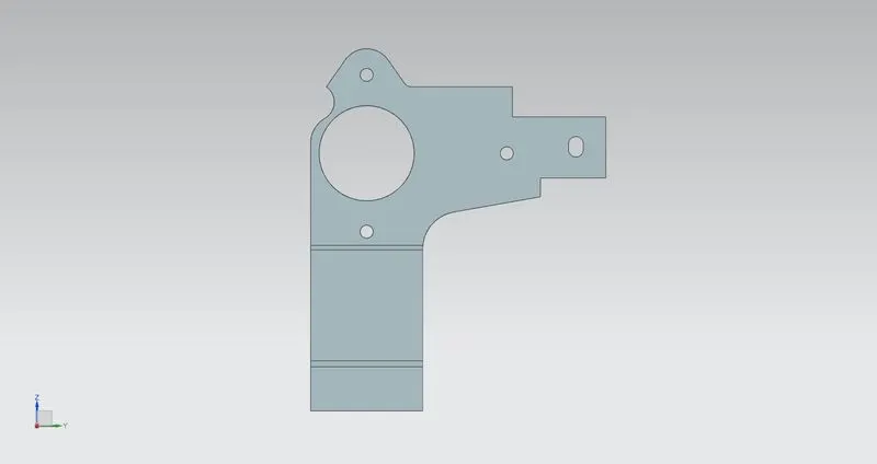
REBEND
Use the Re-bend command to return an unbend feature to its previous bend state. Any features added after the unbend operation are properly repositioned during the re-bend operation.
ADVANCED FLANGE
To add a flange along an edge using a bend angle or a reference face. The edge and reference face can be curved. You can select a single edge or a chain of tangent edges.
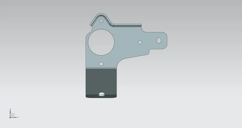
SIMPLE HOLE
To create a simple hole command using by hole feature
GUSSET
To create a stiffening feature on a part. Create strengthening features where extra strength is required in the bend region. Create punched or embossed shapes in bend regions of sheet metal parts. Specify default dimensions for the Gusset feature using customer defaults.
DRAFTING
Which provides tools to create and maintain drawings of the design pattern.
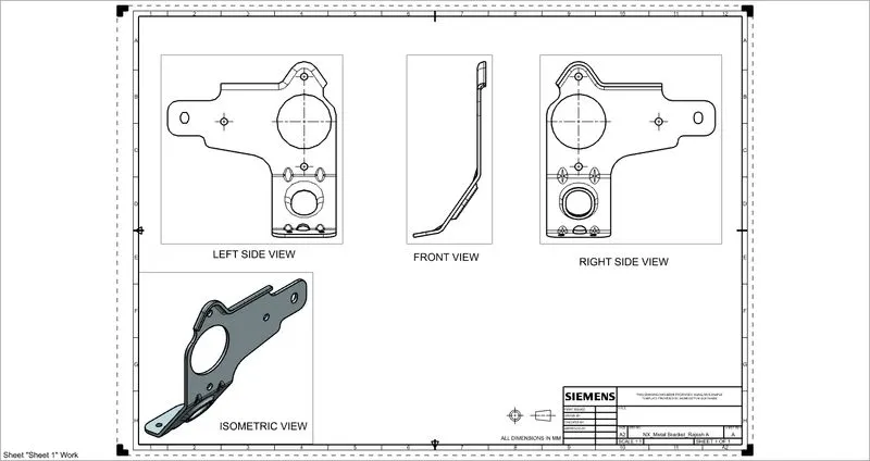
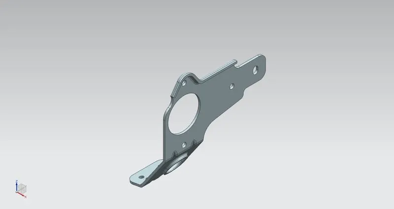
FINAL PRODUCT
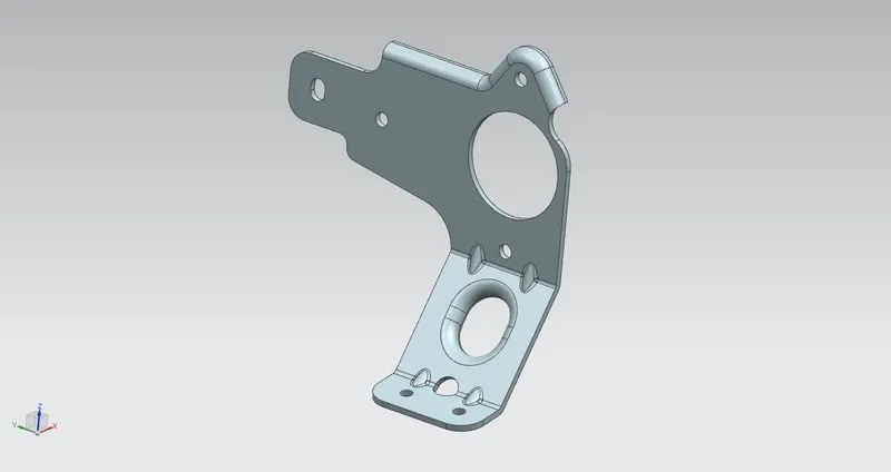
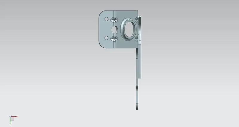
MODEL VIEWS:
FRONT VIEW
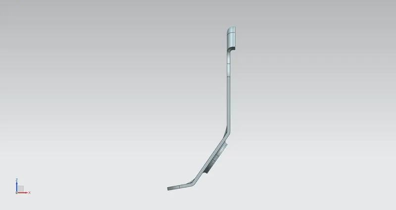
TOP VIEW
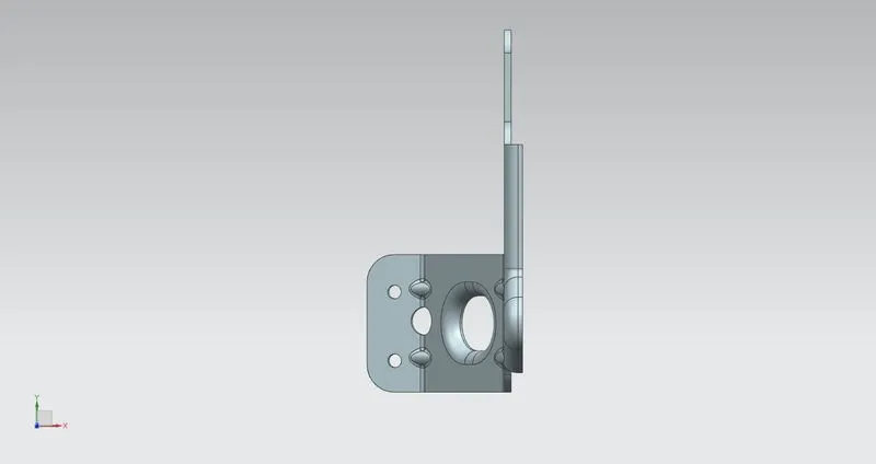
RIGHT SIDE VIEW
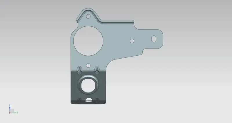
LEFT SIDE VIEW
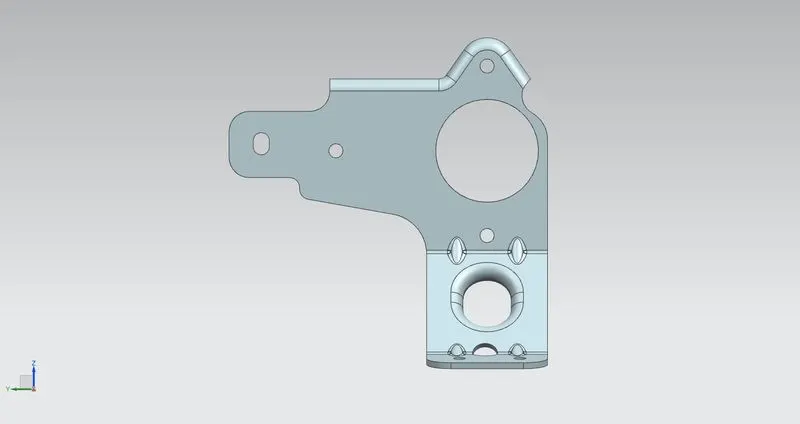
BOTTOM VIEW
ISOMETRIC VIEW
CONCLUSION:
Thus the ‘Sheetmetal Metal Bracket’ design using NX sheet metal application and the results are obtained.