Roof challenge
ROOF DESIGN
Objective:
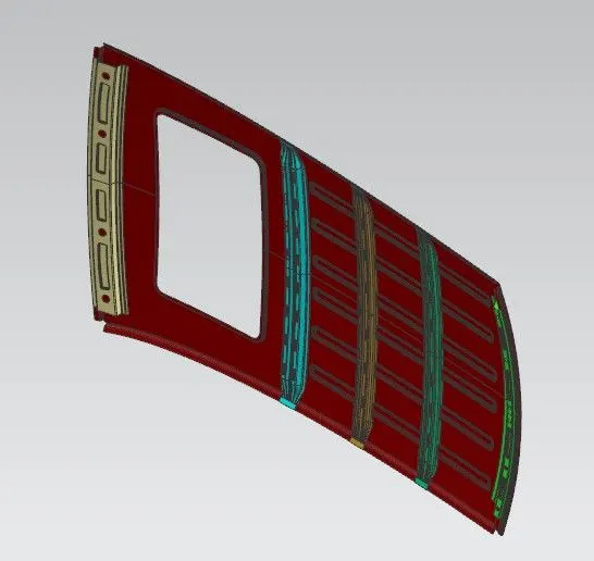
The Main objective is to design a Roof with Roof rails like Front roof rail, centre roof rail with reinforcement rail, bow roof rail 1, Bow roof rail 2 and Rear roof rail. Performing a curvature study on the designed roof and calculating the Heat distortion, Snow load criteria, Section modulus and performing Draft analysis to each designed part using Siemens Nx application.
Introduction:
Here, we are going to study about how to create a Roof with Roof rails like Front roof rail, centre roof rail with reinforcement rail, bow roof rail 1, Bow roof rail 2 and Rear roof rail in siemens Nx Application. Using this application, how we are going to use tools step by step to complete the design. Then complete explanation about tools used to create roof and analysis made on roof.
Design Methodology:
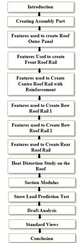
The design methodology of Roof design is explained through flow charts.
Introduction:
Roof:
An automobile roof or car top is the portion of an automobile that placed above the passenger compartment, protecting the vehicle occupants from sun, wind, rain and other external elements.
Sun Roof:
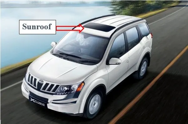
A sunroof is a movable panel that opens to uncover a window in an automobile roof, allowing light and/or fresh air to enter the passenger compartment. Sunroofs can be manually operated or motor driven, and are available in many shapes, sizes and styles. While the term sunroof is now used generically to describe any glass panel in the roof, the term "moonroof" was historically used to describe stationary glass panes rigidly mounted in the roof panel over the passenger compartment. A moonroof has a glass panel that is transparent and usually tinted. Previous terms include Sunshine Roof, Sliding Head and Sliding Roof.
Design Considerations for a Roof:
- Visibility Criteria
- Head Clearance
- Curvature Study
- Heat Distortion and Snow Load Criteria
- Section Modulus
- Draft Analysis
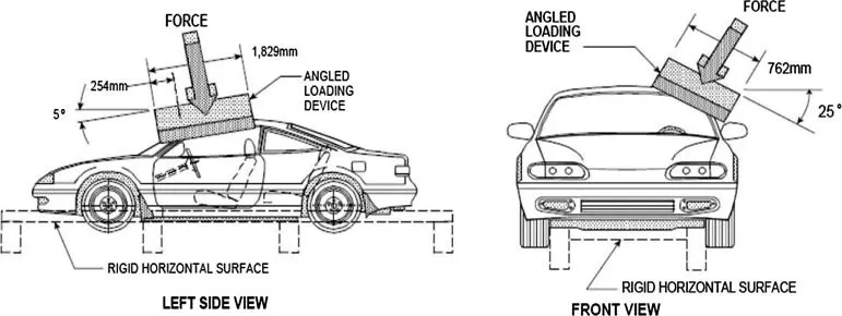
Roof Crush Test:
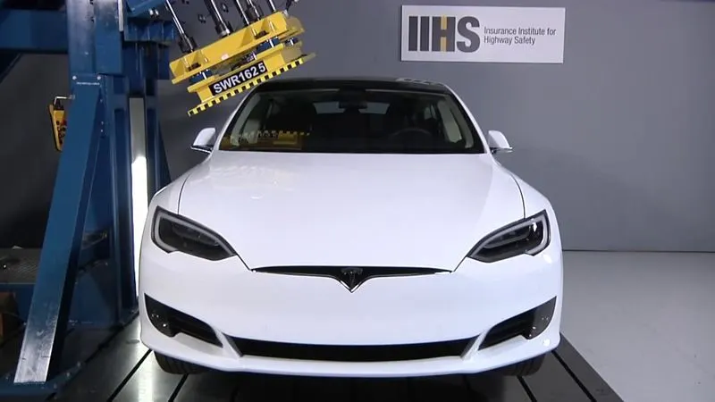
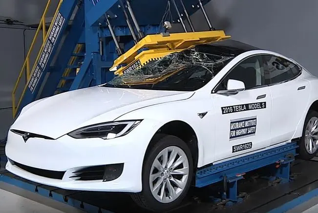
Roof Crush test is the design given by the IIHS (Insurance Institute of Highway Safety). After analysing the many accidents IIHS has then fixed some regulations, that how to perform the crush test.
IIHS gives the rating based up on this test. For this, they consider two points while giving the rating.
- How fast the car reforms to its original shape after the roll over and
- How deep is the protrusion after the roll over?
Goal of Roof Crush Test:
To minimize the protrusion into the occupant compartment, so that the seat belts and the air bags can do their job in protecting the occupant.
Conditions to Follow for Roof Crush Test:
There are two conditions that should be followed for the roof crush test, they are
Initial Condition:
- Close and lock all the doors
- Close all the windows
Second Condition:
Fix the body sill or chassis frame on a hard level surface horizontally.
Method of Applying the Force:
The Load is applied in such a way that 5⁰ is titled from the front end to the rear end and the load will be in 1800 mm in length and 750 mm in width. The load is applied at the position of 25⁰ from the flatness of the roof. The load is applied on the roof for almost 120 secs and the crush speed at which the load applied is 13 mm/sec or less than that value mentioned.
Creating Assembly Part Files:
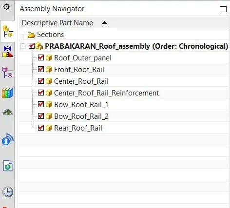
- Start Siemens Nx application to create assembly sheet. Then click ok to start design.
- Clicking on the assembly tab, click on create new icon, the new component file dialog box appears, in that select model part file and name it as Roof Assembly and choose the folder location to save. Then click ok to procced.
- Sample image were attached below for reference.
Features Used to Create Roof Outer Panel:
- Clicking on the Assembly navigator tab, double click on the created part file to start designing.
- Before starting design, we need to download the styling surface design provided to us to create roof design.
- Assigning feature group name as Parent Geometry to the downloaded styling surface body.
- Extract the required body from parent geometry and assigning feature group name as Working Geometry to the extracted body.
- To create a Roof outer panel, we need to follow the master sketch provided to us and required tools to design.
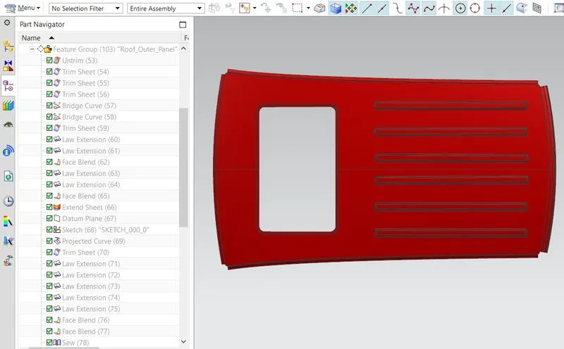
- The following commands were used to create roof outer panel are Untrim, Trim sheet, Bridge Curve, Law extension, Face Blend, Extend Sheet, Datum Plane, Sketch, Projected Curve, Sew, Edge blend, Emboss, Mirror Geometry, Examine Geometry and Thicken.
- Some of the above commands were used repeatedly to complete our design and parameters were changed according to the roof design.
- Applying thickening command to the created part file with the parameters of 0.75 mm.
- Assigning Feature group name as Roof Outer Panel from Untrim (53) command to Thicken (101).
- And Assigning colour to the thickened part.
- The image has been attached below for the reference.
Features Used to Create Front Roof Rail:
- Clicking on the Assembly navigator tab, double click on the created Front Roof Rail part file to start design.
- Unhide the Roof Outer panel to Link with Front Roof Rail part. Using Wave geometry linker, the roof outer panel is linked into the Front roof rail to start design.
- Clicking on the part navigator and selecting the linked body to assign feature group name as Parent Geometry to secure the design.
- Extracting the body from linked body from parent geometry and assigning feature group name as Working Geometry.
- Before starting design of front roof rail, we need to follow the given master sketch parameters.
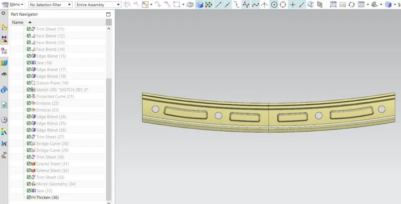
- The commands were used to create Front Roof Rail are Datum Plane, Trim sheet, Face Blend, Edge Blend, Sketch, Projected Curve, Emboss, Bridge curve, extend sheet, Mirror Geometry, Sew, Examine Geometry and Thicken.
- Some of the above commands were used repeatedly to complete our design and parameters were changed according to the front roof rail design parameters.
- Applying thickening command to the created part file with the parameters of 0.75 mm.
- Assigning Feature group name as Front Roof Rail from Datum Plane (9) command to Thicken (36).
- And Assigning colour to the thickened part.
- The image has been attached below for the reference.
Features Used to Create Centre Roof Rail with Reinforcement Rail:
- Clicking on the Assembly navigator tab, double click on the created Centre Roof Rail part file to start design.
- Unhide the Roof Outer panel to Link with Centre Roof Rail part. Using Wave geometry linker, the roof outer panel is linked into the centre roof rail to start design.
- Clicking on the part navigator and selecting the linked body to assign feature group name as Parent Geometry to secure the design.
- Extracting the body from linked body from parent geometry and assigning feature group name as Working Geometry.
- The Commands were used to create centre roof rail are Datum plane, Intersection Curves, Offset face in curve, Offset surface, Trim sheet, Through Curves, Face Blend, Sketch, Projected Curve, Bridge curves, Studio Surface, extend sheet, Trim Body, Sew, examine geometry, Mirror Geometry and Thicken.
- Some of the above commands were used repeatedly to complete our design and parameters were changed according to the required shape.
- Applying thickening command to the created part file with the parameters of 0.75 mm.
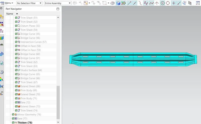
- Assigning Feature group name as Centre Roof Rail from Datum Plane (7) command to Thicken (78).
- And Assigning colour to the thickened part.
- The image has been attached below for the reference.
Reinforcement Rail:
- Clicking on the Assembly navigator tab, double click on the created Centre Roof Rail Reinforcement part file to start design.
- Unhide the Roof Outer panel to Link with Centre Roof Rail Reinforcement part. Using Wave geometry linker, the roof outer panel is linked into the centre roof rail reinforcement to start design.
- Clicking on the part navigator and selecting the linked body to assign feature group name as Parent Geometry to secure the design.
- Extracting the body from linked body from parent geometry and assigning feature group name as Working Geometry.
- The Commands were used to create centre roof rail reinforcement are Offset face in curve, Offset surface, Trim sheet, Through Curves, Face Blend, Sketch, Projected Curve, Bridge curves, Emboss, Edge Blend, Sew, examine geometry, Mirror Geometry and Thicken.
- Some of the above commands were used repeatedly to complete our design and parameters were changed according to the required shape.
- Applying thickening command to the created part file with the parameters of 0.75 mm.
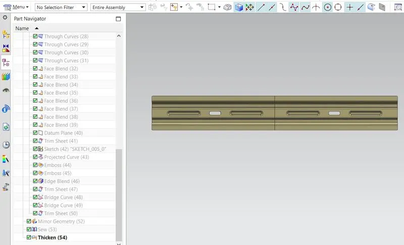
- Assigning Feature group name as Centre Roof Rail Reinforcement from Offset Curve in Face (5) command to Thicken (78).
- And Assigning colour to the thickened part.
- The image has been attached below for the reference.
Features Used to Create Bow Roof Rail 1:
- Clicking on the Assembly navigator tab, double click on the created Bow Roof Rail 1-part file to start design.
- Unhide the Roof Outer panel to Link with Bow Roof Rail-1 part. Using Wave geometry linker, the roof outer panel is linked into the Bow Roof Rail-1 to start design.
- Clicking on the part navigator and selecting the linked body to assign feature group name as Parent Geometry to secure the design.
- Extracting the body from linked body from parent geometry and assigning feature group name as Working Geometry.
- The Commands were used to create Bow Roof Rail-1 are Datum plane, Intersection Curves, Offset face in curve, Offset surface, Trim sheet, Through Curves, Face Blend, Sketch, Projected Curve, Bridge curves, Studio Surface, extend sheet, Trim Body, Sew, examine geometry, Mirror Geometry and Thicken.
- Some of the above commands were used repeatedly to complete our design and parameters were changed according to the required shape.
- Applying thickening command to the created part file with the parameters of 0.75 mm.
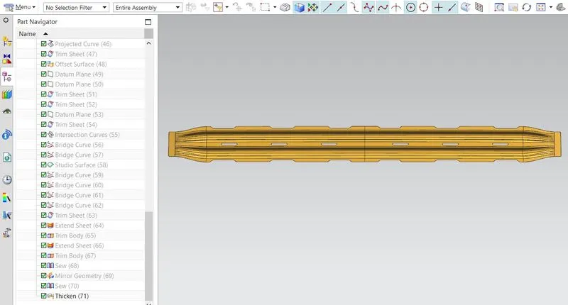
- Assigning Feature group name as Bow Roof Rail-1 from Datum Plane (6) command to Thicken (71).
- And Assigning colour to the thickened part.
- The image has been attached below for the reference.
Features Used to Create Bow Roof Rail 2:
- Clicking on the Assembly navigator tab, double click on the created Bow Roof Rail 2-part file to start design.
- Unhide the Roof Outer panel to Link with Bow Roof Rail-2 part. Using Wave geometry linker, the roof outer panel is linked into the Bow Roof Rail-2 to start design.
- Clicking on the part navigator and selecting the linked body to assign feature group name as Parent Geometry to secure the design.
- Extracting the body from linked body from parent geometry and assigning feature group name as Working Geometry.
- The Commands were used to create Bow Roof Rail-2 are Datum plane, Intersection Curves, Offset face in curve, Offset surface, Trim sheet, Through Curves, Face Blend, Sketch, Projected Curve, Bridge curves, Studio Surface, extend sheet, Trim Body, Sew, examine geometry, Mirror Geometry and Thicken.
- Some of the above commands were used repeatedly to complete our design and parameters were changed according to the required shape.
- Applying thickening command to the created part file with the parameters of 0.75 mm.
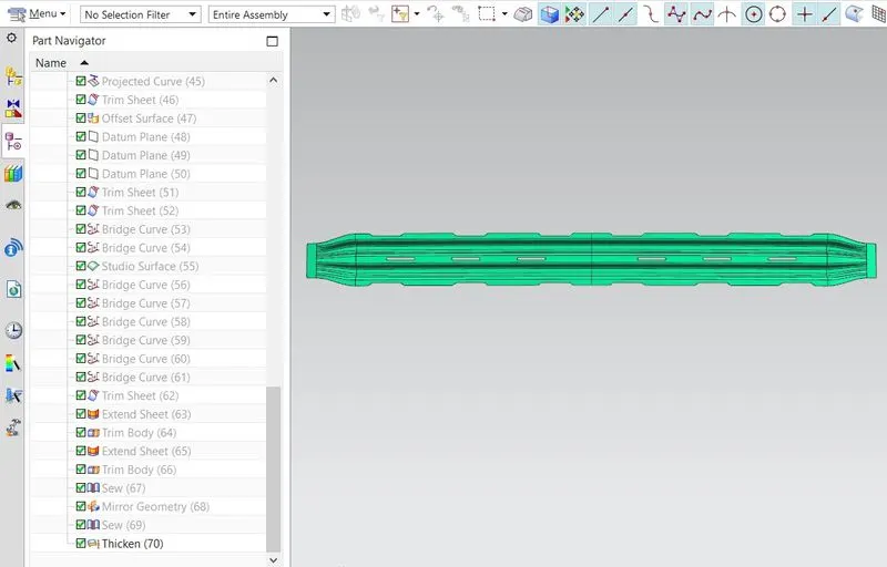
- Assigning Feature group name as Bow Roof Rail-2 from Datum Plane (6) command to Thicken (70).
- And Assigning colour to the thickened part.
- The image has been attached below for the reference.
Features Used to Create Rear Roof Rail:
- Clicking on the Assembly navigator tab, double click on the created Rear Roof Rail part file to start design.
- Unhide the Roof Outer panel to Link with Rear Roof Rail part. Using Wave geometry linker, the roof outer panel is linked into the Rear roof rail to start design.
- Clicking on the part navigator and selecting the linked body to assign feature group name as Parent Geometry to secure the design.
- Extracting the body from linked body from parent geometry and assigning feature group name as Working Geometry.
- Before starting design of rear roof rail, we need to follow the given master sketch parameters.
- The commands were used to create Rear Roof Rail are Offset face in curves, Offset Surface, Trim sheet, Through Curves, Law extension, Trim & Extend, Face Blend, Edge Blend, Sketch, Projected Curve, Emboss, Bridge curves, extend sheet, Mirror Geometry, Sew, Examine Geometry and Thicken.
- Some of the above commands were used repeatedly to complete our design and parameters were changed according to the Rear roof rail design parameters.
- Applying thickening command to the created part file with the parameters of 0.75 mm.
- Assigning Feature group name as Front Roof Rail from Offset Curve in face (6) command to Thicken (46).
- And Assigning colour to the thickened part.
- The image has been attached below for the reference.
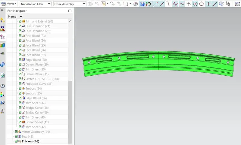
Heat Distortion Study on the Roof:
The heat distortion study plays a major role in sheet metal usage. Heat distortion temperature is a temperature limit above which the material cannot be used for the structural applications. This study is used to predict the heat distortion temperature at where the material starts to soften, when exposed to a fixed load at elevated temperature. In order to avoid bending or damages on the roof, based on the heat distortion temperature, this study will predict the bow roof position which helps to strengthen the roof.
Bow-Roof Prediction Formula:
W= [1.73x10^(-3) x L] + [1.85x10^(-8) x (R^2)/t] + [1.10x10^(-3) x l]-2.68
Judgement Condition: OK< 2.7> 3.1
Where,
L = Roof Length in X-Direction[mm] (Roof dimension in 0-Y)
R = Roof curvature
R = 2(Rx*Ry)/(Rx+Ry)
Rx = X curvature
Ry = Y curvature
t = Roof plate thickness [mm]
l = Bow Roof Span [mm]
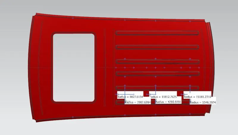
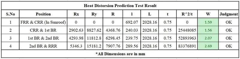
From the above table, we could see that “W’’ is passing the judgement condition.
Section Modulus:
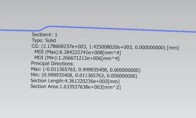
Section modulus is a geometric property for a given cross-section used in the design of beams. Other geometric properties used in the design include an area for tension, radius of gyration for compression, and moment of inertia for stiffness. The section modulus is defined as
S = I/y
Where,
S = Section modulus
I = Moment of Inertia
Y = Distance from the neutral axis to any given part.
Section Modulus for Roof Outer Panel:

Section Modulus for Front Roof Rail:
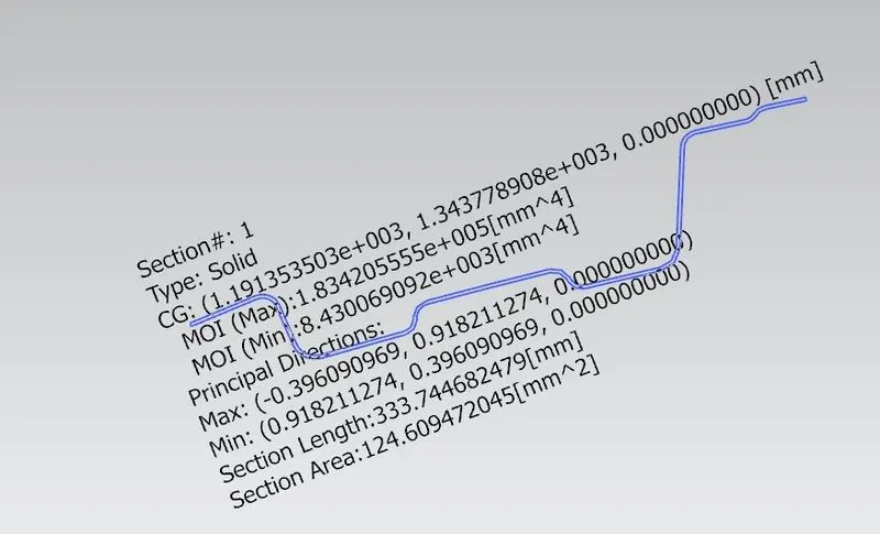
Minimum Moment of Inertia Iy = 8430.07
Section Modulus for Centre Roof Rail with Reinforcement:
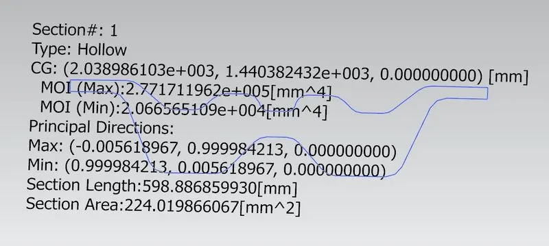
Minimum Moment of Inertia Iy = 20665.65
Section Modulus for Bow Roof Rail 1:
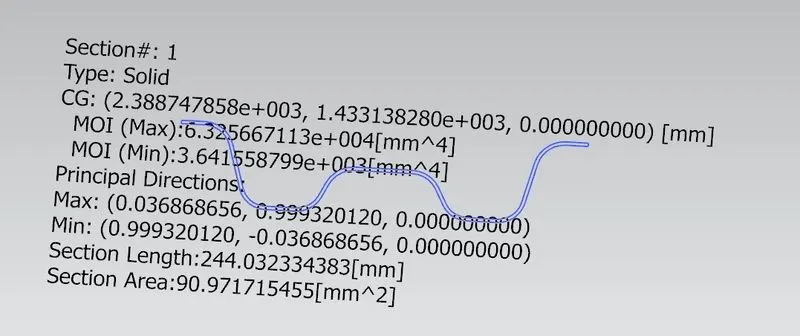
Minimum Moment of Inertia Iy = 3641.56
Section Modulus for Bow Roof Rail 2:
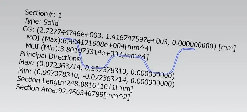
Minimum Moment of Inertia Iy = 3801.07
Section Modulus for Rear Roof Rail:
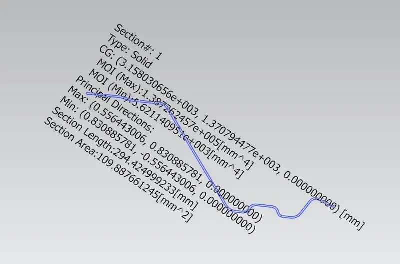
Minimum Moment of Inertia Iy = 5621.14
Snow Load Prediction Test:
Snow load Prediction formula:
Qr = [Iy x t2] / [α x s x [(Rx + Ry)/2]2 x 10-8]
Note: The Qr value given over here is correct. There was a typo error in the formula given in the video.
Where,
α = My x Lx2 x 10-12, My = Y(Ly-Y)
Judgement condition = Qr ≥ 3.1
250 ≤ s ≤ 380
t = Roof plate thickness [mm]
Ly = Distance between the front and rear roof Rails on the Vehicle along with 0Y [mm]
Length of Roof panel with the centre point between Roof rail Front /Rear as the reference point of the front and the rear.
Lx = Distance between the Left and Right end of the roof on the Roof BOW [mm]
Width of the roof panel exposed on the surface.
Y = Distance from Front Roof Rail to Roof BOW [mm]
s = Distance for which Roof BOW bears divided load [mm]
s = L1/2 + L2/2
Iy = Geometrical moment of inertia of Roof BOW (Y cross-section) [mm4]
Rx = Lateral direction curvature radius of roof panel Y cross-section on Roof BOW [mm]
Roof panel curvature Radius of the Length Lx in Front view.
Ry = Longitudinal Direction curvature radius of the Roof panel X cross-section on Roof BOW [mm]
Roof panel X curvature radius of length s in Side view.
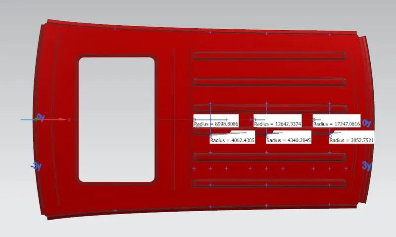

From the above table,
- First case & Fourth case won't satisfy the conditions because, in 1st case Rx & Ry = 0 (i.e., sunroof placed on the outer roof panel) and the 4th case there is no L2 value. So both cases were not considered.
- And the 2nd case & 3rd case satisfy the judgement condition.
Draft Analysis:
Draft Analysis is done to check whether the part is manufacturable or not. It is not sure shot confirmation that the part is manufacturable, but it is used to check the draft angle on the part. The minimum draft angle is to maintain for sheet metal is 7 mm. The tooling direction for the analysis is perpendicular to the designed part.
Draft Analysis on Roof Outer Panel:
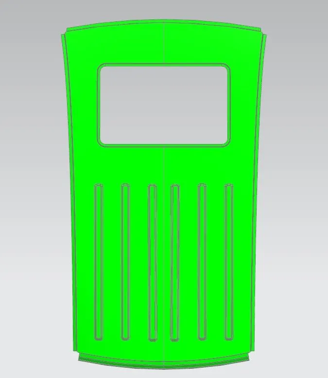
- The above part is able to manufacture.
Draft analysis on Front Roof Rail:
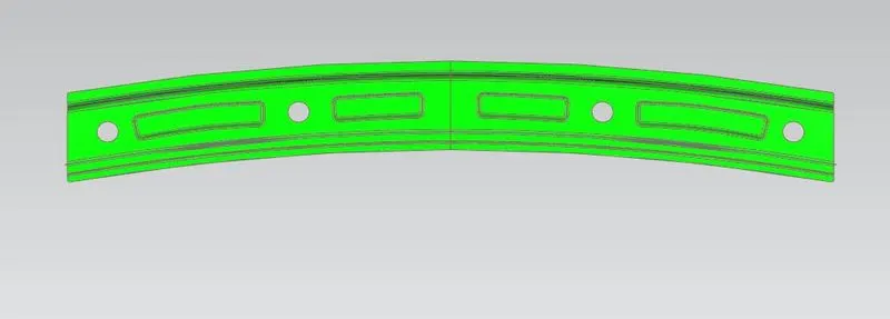
- The above part is able to manufacture.
Draft analysis on Centre Roof Rail:
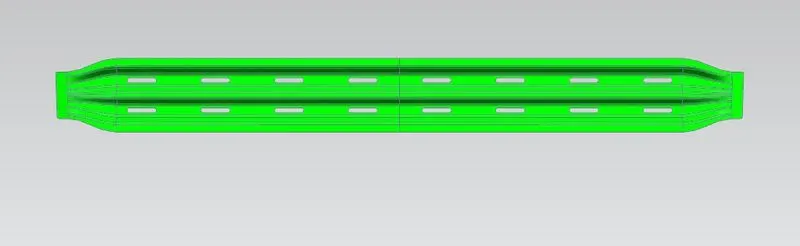
- The above part is able to manufacture.
Draft analysis on Centre Roof Rail Reinforcement:
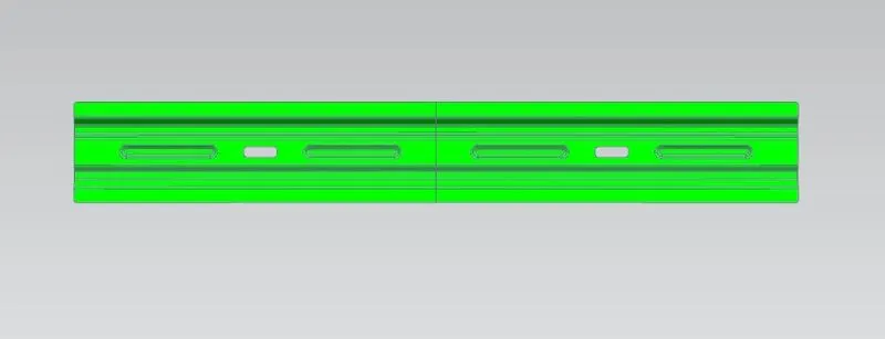
- The above part is able to manufacture.
Draft analysis on Bow Roof Rail 1:
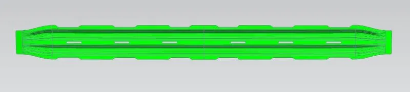
- The above part is able to manufacture.
Draft analysis on Bow Roof Rail 2:
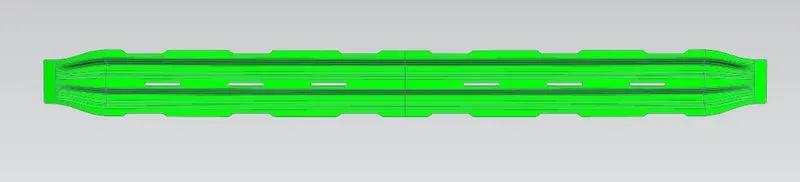
- The above part is able to manufacture.
Draft analysis on Rear Roof Rail:
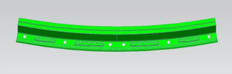
- The above part is able to manufacture.
Standard Views:
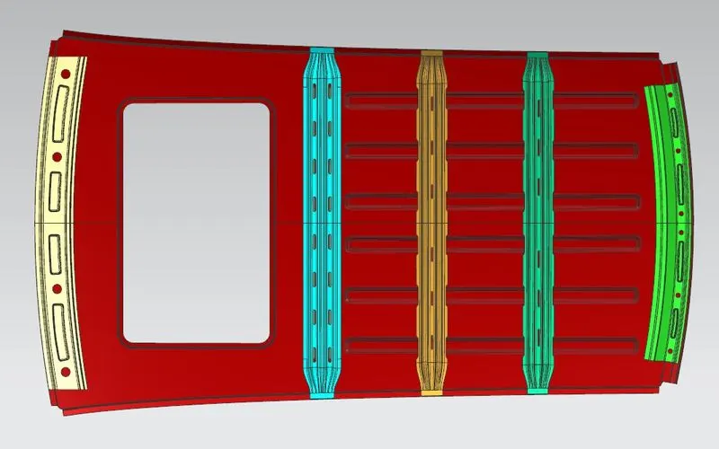
Front View:
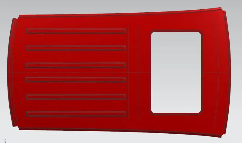
Back View:
Top View:

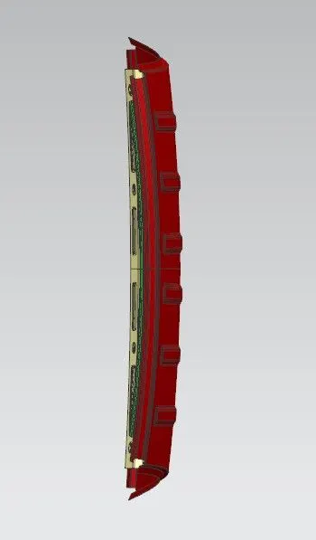
Side View:
Isometric View:
Conclusion:
Finally the Roof design has been completed successfully with the provided styling surface and master sketch parameters. Hence, proved the curvature study, heat distortion, snow load criteria, section modulus and draft analysis.