Roof challenge
Roof design
Objective:
To create a detailed 3D model of Automobile Roof using siemens NX.
Introduction:
In this project a detailed model of an automobile roof is created using Siemens NX in-order to understand and familiarize with different tools and methods of modelling. Roof is one of the main components of an automobile as it provides safety and to the passengers. The roof is designed in such a way that the passengers are protected from any falling object on the car. The roof panel consists of four main components.
- Front roof rail: The front roof rail is connected to the front end of the ditch area. The front roof rail is one of the three main rails (front, centre and rear roof rail) which absorb most of the load.
- Centre roof rail: The centre rail serves the purpose of providing support to the centre part of the roof which is also the most susceptible region of the roof. The centre roof rail consists of two different cross sections for more load absorbing capacity.
- Bow roof rails: the bow roof rails are used to support the roof in areas between the centre and the extreme ends of the roof. These rails provide extra support to the roof as well as help maintain the shape of the ditch area intact.
- Rear roof rail: The rear roof rail is connected to the rear end of the ditch area. This rail provides support to the rear end of the roof.
- Ditch area: the ditch area is the panel of roof which is connected to all the rails. It has a thickness of .75 mm and is based on visibility criteria, windshield clearance and back door placement.
Design Methodology:
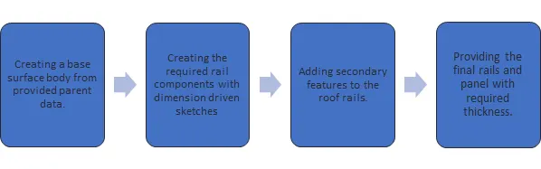
Description:
The roof design consists of inner rail supports and outer panel.
- Front roof rail:
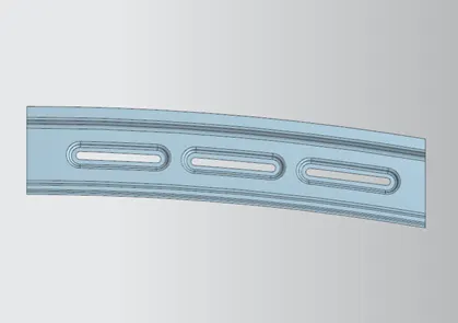
The front roof rail is dimensioned based on the head room clearance criteria as well as visibility criteria.
The rail has a .75 mm thickness and can vary between 60-100 mm in length.
The emboss are given to strengthen the rail surface and to reduce the material used in the surface.
- Centre roof rail:
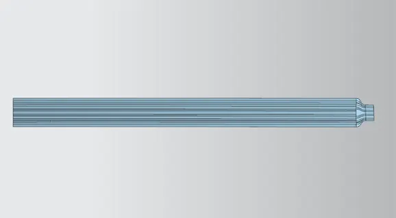
Centre roof rail consists of two different cross sections for better strength and resistance against bending.
Extra material is kept at the edges for fixing the ditch area with the rail with mastic or spot welds.
The thickness of the rail is .75 mm.
- Bow roof rail:
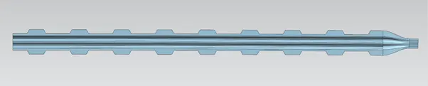
Bow roof rails are used for support.
The edges are provided with mastic points for connecting the rail to the ditch area.
- Rear roof rail:
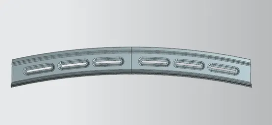
The rear roof rail is similar to the front roof rail. It consists of emboss for better strength and less weight. The thickness of the sheet is .75 mm.
- Ditch area:
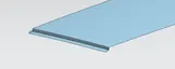
The inner panel of the roof assembly with a thickness value of .75mm.
The roof rails are attached to this panel via mastics or spot welds.
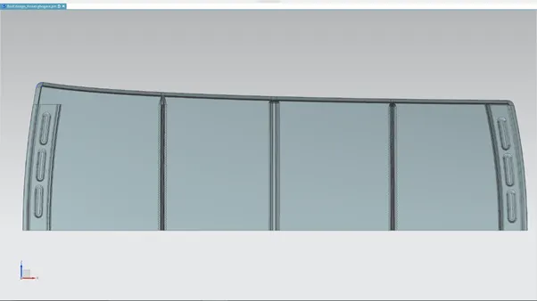
Complete assembly view:
Analysis:
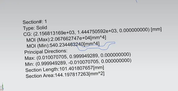
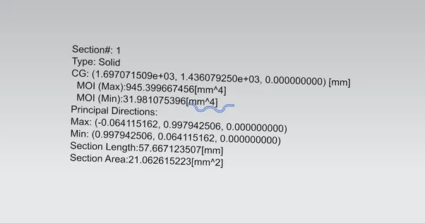
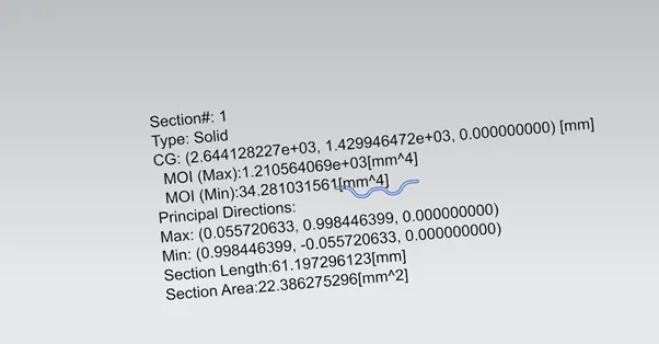
Cross sectional analysis of the roof rails is given below.
- Centre roof rail:
- Bow roof rails:
1.
2.
Bow-roof prediction:
Using the below given formula, the location of bow roof can be determined.
W = [1.73 x 10^(-3) x L] + [1.85 x 10^(-8) x (R^2)/t] + [ 1.10x10^(-3) x l] - 2.68
With the judgement condition of w<2.7>3.1, we get the following result in the table:
Where
L = Roof Length in X-Direction[mm](Roof dimension in 0-Y)
R = Roof curvature
R = 2(Rx*Ry)/(Rx+Ry)
Rx = X curvature
Ry = Y curvature
t = Roof plate thickness [mm]
l = Bow Roof Span [mm]
|
s.no |
Bow |
Rx |
Ry |
R |
l |
L |
t |
W |
Judgement |
|
1. |
FR – bow 1 |
6264 |
2778.9 |
3849.87 |
443.7 |
2029.1 |
.75 |
1.71 |
OK |
|
2. |
Bow 1- CR |
4913.2 |
6764 |
5691.93 |
423.8 |
2029.1 |
.75 |
2.1 |
OK |
|
3. |
CR – Bow 2 |
4059.6 |
10960 |
5924.68 |
451.6 |
2029.1 |
.75 |
2.2 |
OK |
|
4. |
Bow 2 - RR |
3293.6 |
16288.6 |
5479.27 |
420 |
2029.1 |
.75 |
2.04 |
OK |
Snow load criteria:
The snow load criteria is to determine the roof strength to regain its original shape after bending.
The formula for snow load criteria is given below:
Qr = [Iy x t^2] / [α x s x [(Rx + Ry)/2]^2 x 10^-8]
Where
α = My x Lx^2 x 10^-12, My = Y(Ly-Y)
Judgement condition = Qr ≥ 3.1
250 ≤ s ≤ 380
t = Roof plate thickness [mm]
Ly = Distance between the front and rear roof Rails on the Vehicle along with 0Y[mm]
Length of Roof panel with the centre point between Roof rail Front /Rear as the reference point of the front and the rear.
Lx = Distance between the Left and Right end of the roof on the Roof BOW [mm]
Width of the roof panel exposed on the surface.
Y = Distance from Front Roof Rail to Roof BOW [mm]
s = Distance for which Roof BOW bears divided load [mm]
s = L1/2 + L2/2
Iy = Geometrical moment of inertia of Roof BOW (Y cross-section) [mm4]
Rx = Lateral direction curvature radius of roof panel Y cross-section on Roof BOW [mm]
Roof panel curvature Radius of the Length Lx in Front view
Ry = Longitudinal Direction curvature radius of the Roof panel X cross-section on Roof BOW [mm]
|
s.no |
Bow |
Iy |
α |
Lx |
Ly |
y |
s |
Rx |
Ry |
t |
Qr |
Judgement |
|
1. |
FR – bow 1 |
31.98 |
1.001 |
1133.46 |
2029.1 |
515 |
487.5 |
5583 |
2728.17 |
.75 |
3.34 |
ok |
|
2. |
Bow 1 - CR |
540.23 |
.8481 |
1083.98 |
2029.1 |
460 |
473.7 |
3852 |
5540 |
.75 |
3.43 |
ok |
|
3. |
CR – bow 2 |
34.28 |
.841 |
1056.87 |
2029.1 |
487.4 |
490.7 |
3819.5 |
10674.4 |
.75 |
3.2 |
ok |
Conclusion:
Thus after the analysis of the roof section, we conclude that the designed roof model is acceptable and fits within the given safety criteria.