Roof challenge
AIM: DESIGNING A CAR ROOF WITH HEAT DISTORTION AND SNOW LOAD TEST
INTRODUCTION: The roof of the car is the portion of an automobile that is placed directly above the passenger compartment, protecting the vehicle occupants from different weather conditions and external objects.
MASTER SECTION
Front roof rail
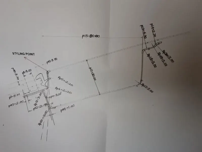
Rear roof rail
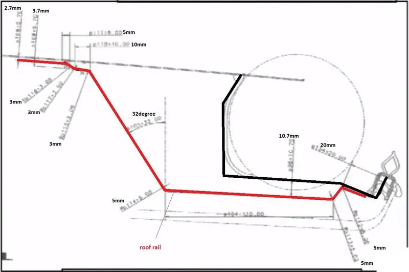
Designing the roof - ditch area
- the ditch area of the roof was created by keeping the data of the master sketch in mind
- the ditch area has a draft angle of 3 degrees and a thickness of 0.75 was given to it
- ditch area is the extended surface of the main roof panel
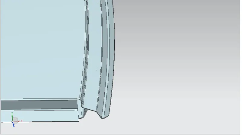
Front roof rail
- the front roof rail joins the windshield, with the roof panel and it must be designed such that it does not hinder the visibility
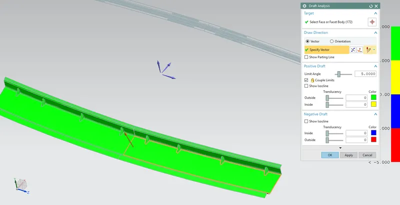
- the front roof was designed by giving a draft value of more than 5 degrees for manufacturability
- surfaces are offset according to the need
- additional darts were provided in order to increase the strength
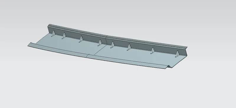
Draft analysis of front roof rail
Bow roof rails
- all the bow roofs were placed in between the front and back roof rails
- since the roof is a long sheet of metal bows are added to increase the strength of the roof
- bow roofs are provided with mastic surface
- emboss is given to increase the strength of the bow rail
Bow roof rail 1
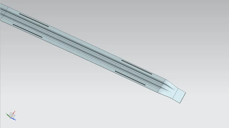
Bow roof rail 1 draft analysis
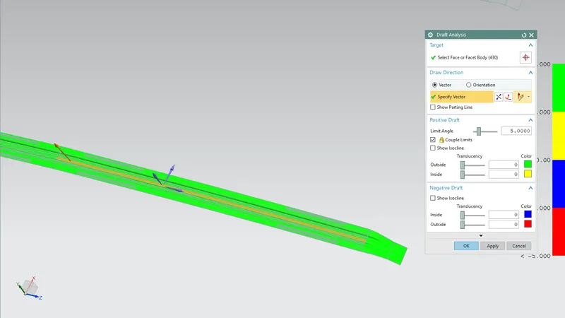
Bow roof rail 2
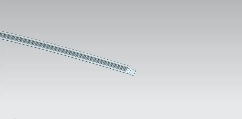
Bow roof rail 2 draft analysis
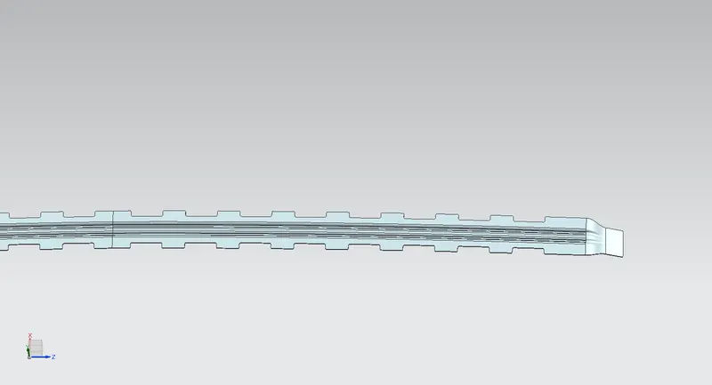
Centre roof rail and reinforcement
- it is placed in between bow roof 1 and bow roof 2
- reinforcement is given to increase the strength of the roof at the centre
- reinforcement is added to increase the moi of the part
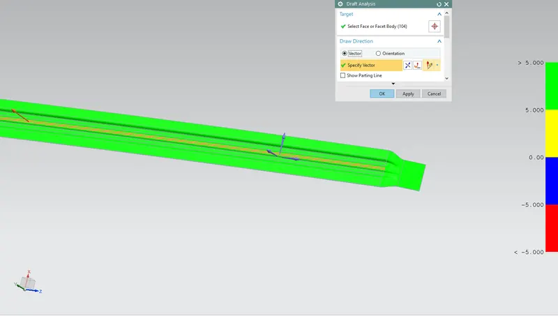
draft analysis of centre roof rail
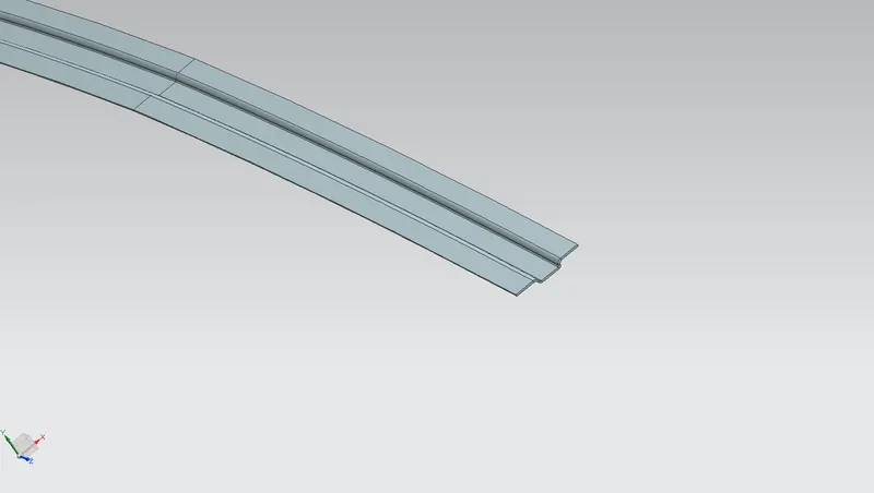
reinforcement of centre roof rail
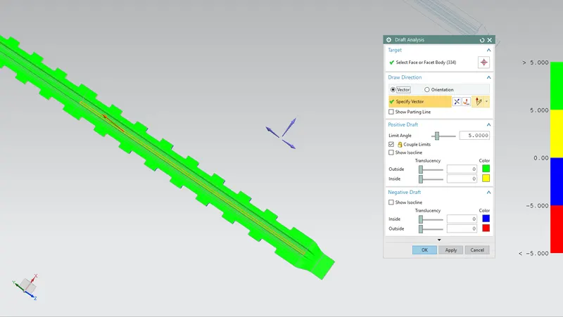
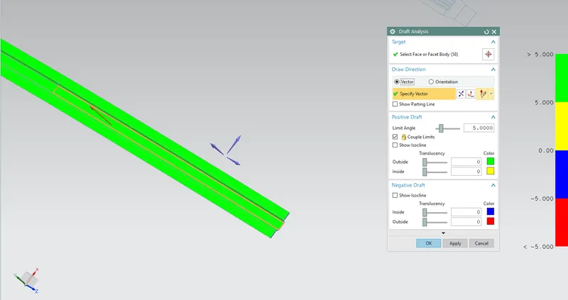
draft analysis of reinforcement
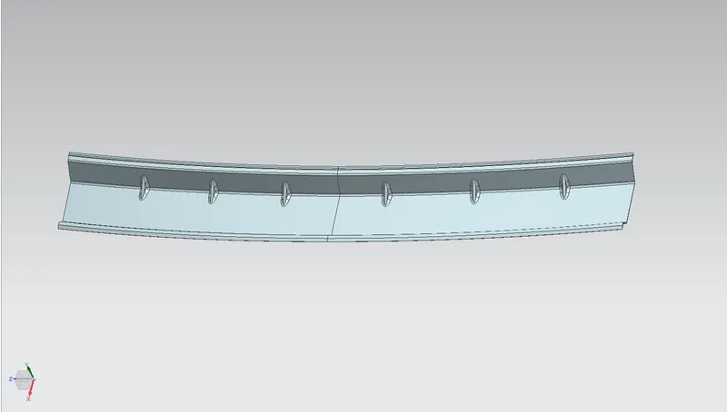
Rear roof rail
- the rear roof is designed using the master section and also the back door clearance in consideration
- spot welding is used to join the back door with the roof
- darts are added to the part to increase the strength of the part
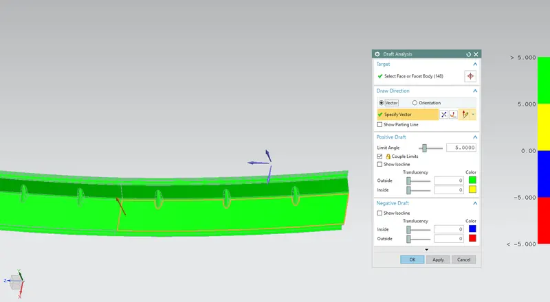
Draft analysis of rear roof rail
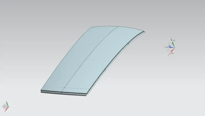
Roof outer panel
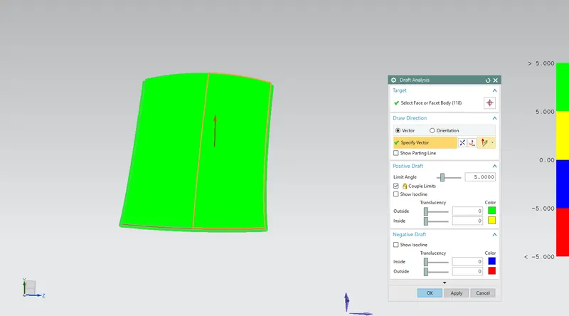
Roof outer panel draft analysis
Section modulus analysis
Front roof analysis
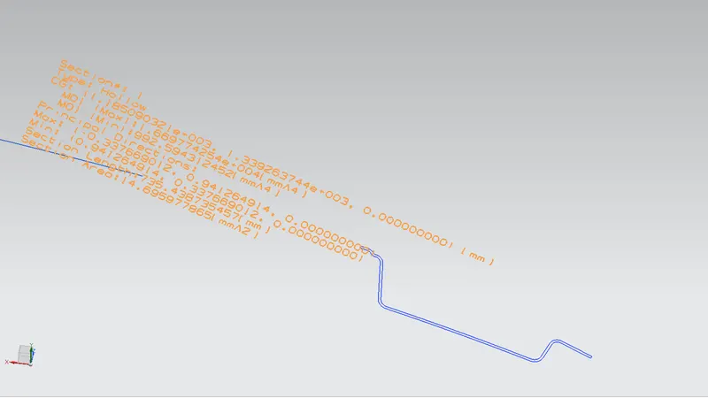
Bow roof rail 1
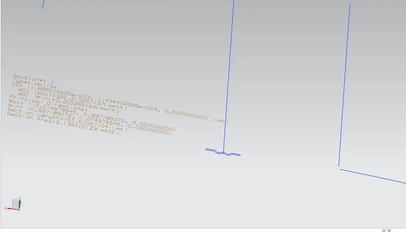
centre roof rail and reinforcement
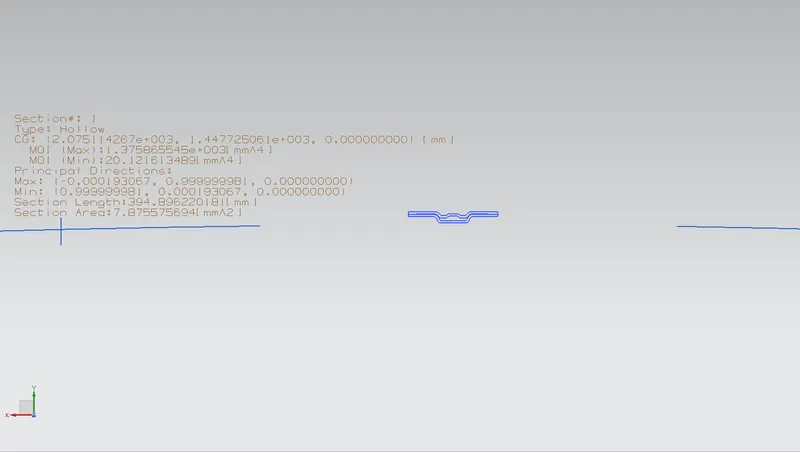
bow roof rail 2
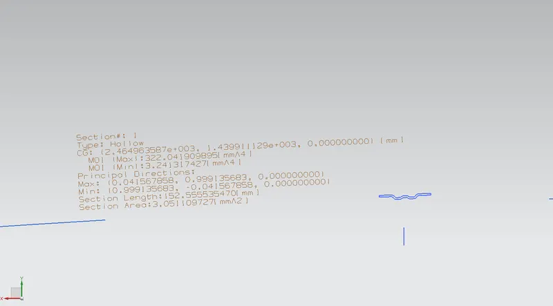
rear roof rail
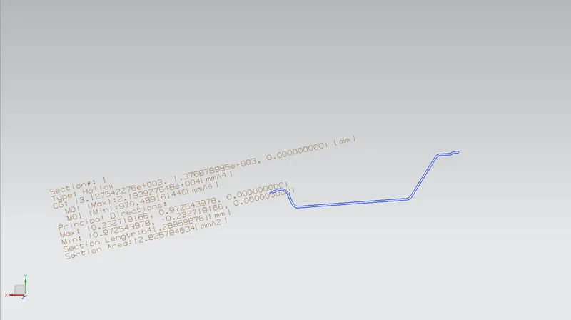
Curvature study and heat distortion criterion
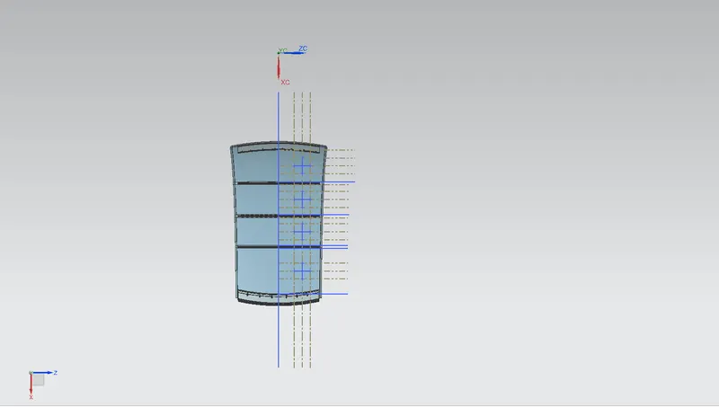
Bow – roof prediction Formula
W = [1.73 x 10^(-3) x L] + [1.85 x 10^(-8) x (R^2)/t] + [ 1.10x10^(-3) x l] - 2.68
Judgement Condition : OK< 2.7> 3.1
Where
L = Roof Length in X-Direction[mm](Roof dimension in 0-Y)
R = Roof curvature
R = 2(Rx*Ry)/(Rx+Ry)
Rx = X curvature
Ry = Y curvature
t = Roof plate thickness [mm]
l = Bow Roof Span [mm]
CALCULATION TABLE
S.NO BOW Rx Ry I L t W RESULT
1 FR & 1ST 7812.51 2013.63 404 2033.87 0.75 1.53 OK
2 1ST & CTR 6699.99 5246.90 380 2033.87 0.75 2.11 OK
3 CTR & 2ND 4935.03 8519.57 350 2033.87 0.75 2.18 OK
4 2ND & RR 3689.57 12909.61 597 2033.87 0.75 2.30 OK
Snow load criterion
Qr = [Iy x t2] / [α x s x [(Rx + Ry)/2]2 x 10-8]
Note: The Qr value given over here is correct. There was a typo error in the formula given in the video.
Where
α = My x Lx2 x 10-12 , My = Y(Ly-Y)
Judgement condition = Qr ≥ 3.1
250 ≤ s ≤ 380
t = Roof plate thickness [mm]
Ly = Distance between the front and rear roof Rails on the Vehicle along with 0Y[mm]
Length of Roof panel with the centre point between Roof rail Front /Rear as the reference point of the front and the rear.
Lx = Distance between the Left and Right end of the roof on the Roof BOW [mm]
Width of the roof panel exposed on the surface.
Y = Distance front Front Roof Rail to Roof BOW[mm]
s = Distance for which Roof BOW bears divided load [mm]
s = L1/2 + L2/2
Iy = Geometrical moment of inertia of Roof BOW (Y cross-section )[mm4]
Rx = Lateral direction curvature radius of roof panel Y cross-section on Roof BOW [mm]
Roof panel curvature Radius of the Length Lx in Front view
Ry = Longitudinal Direction curvature radius of the Roof panel X cross-section on Roof BOW [mm]
Roof panel X curvature radius of length s in Side view
S.NO BOWs Iy α Lx Ly Y S Rx Ry t Qr DETERMINATION
1 FR & 1ST 320.52 0.54 1136.73 2033.87 234.2 262.55 7868.51 2048.17 0.75 5.78 OK
2 1ST & CTR 201.2 0.50 1089.13 2033.87 210.09 210.15 6186.44 4972.03 0.75 3.46 OK
3 CTR & 2ND 201.2 0.40 1064.28 2033.87 195.02 195 4681.47 8607.39 0.75 3.28 OK
4 2ND & RR - 0.00 - 2033.87 336.2 336.51 - - 0.75 - -
From the above results, we can conclude that the part will satisfy both the criterion
Conclusion
for the given roof stylus surface all the flanges, bow roofs and reinforcement were created with the help of a master section sketch also the draft analysis for the parts was performed , the curvature study was carried out to determine the bow roof placements and the heat distortion and snow load criterions were performed successfully