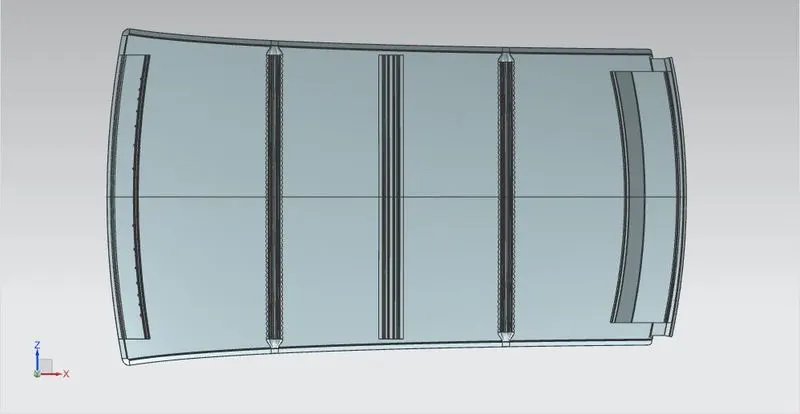
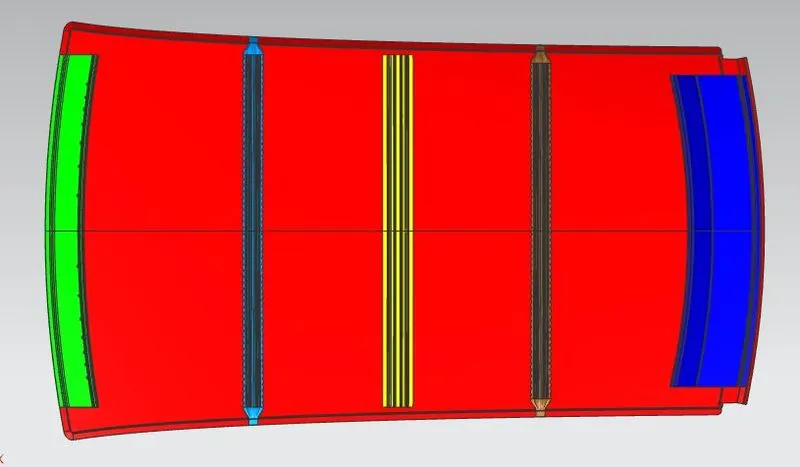
Roof challenge
Design of Automobile Roof and it's components using NX CAD
Introduction:
The roof is part which starts from A-pillar and goes upto the D-pillar. The roofs purpose is to provide cover to the passenger in side the car and protect the passengers from elements like sun, rain, wind, etc. The roof also prevents unwanted objects from falling inside the car.
Objective:
- To design an automobile roof.
- Make its components using NX CAD.
- Find section modulus for bow roof 1 and 2, Center roof rail.
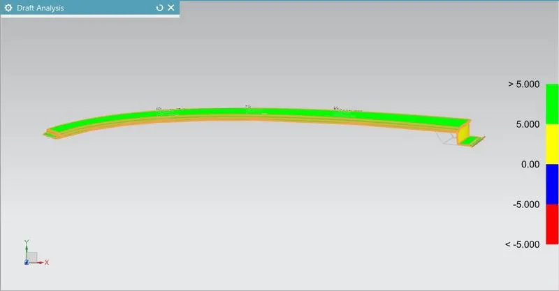
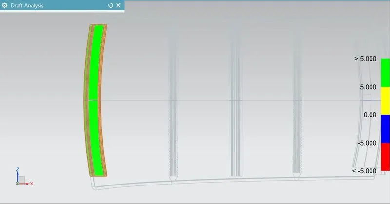
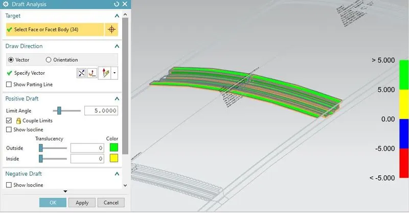
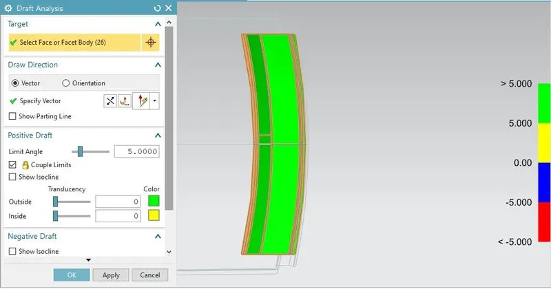
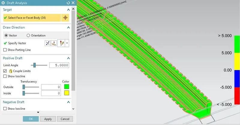
- Performing draft analysis
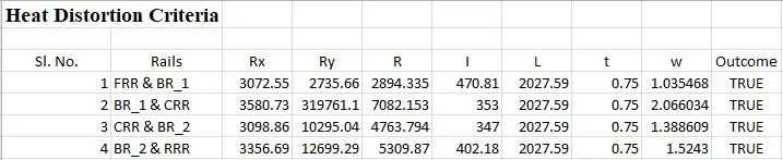
- Checking heat distortion cirteria
- Checkinh snow load criteria for the roof.
- Check wheather the roof passes the above two criteria.
Commands and tools used:
- Sketch
- Datum
- Intersection curves
- Projected curves
- Through curves
- swept
- Studio surfaces
- Through curve mesh
- Extend sheet
- Trim sheet
- Trim and Extend
- Law extension
- Offset surface
- Extract surface
- Untrim
- Face blend
- Edge blend
- Thicken
- sew
- Bridge curve
- offset curve in face
- curve length
- composite curve
- section inertia analysis
- Draft analysis
Components of the roof:
- Roof
- Front roof rail
- Center roof rail
- Rear roof rail
- Bow roof 1
- Bow roof 2
Note 1: The number of bow roofs depend on the roof length and curvature.
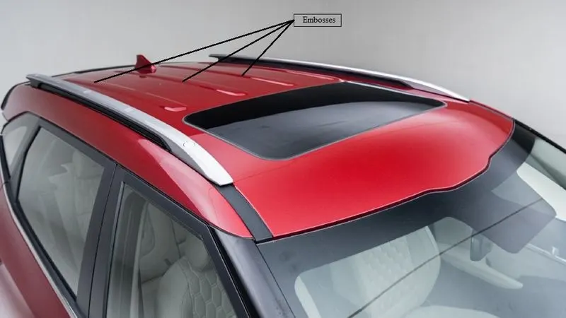
Note 2: The roof outer panel can also have embosses of different shapes to increase the strength.
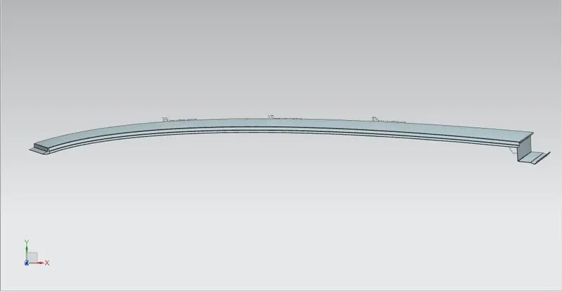
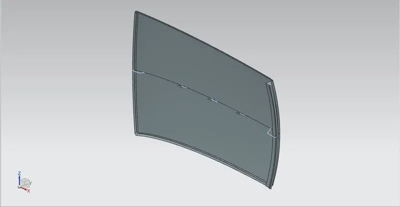
Roof outer panel design:
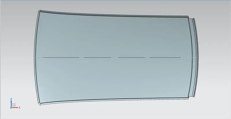
The roof outer panel is a styling panel which is visible in the car. This panel has ditch area to attach all its components. This panel also has emboses for strengthning it. The roof outer panel is direct contact with the outside eviornment.
Thickness: 0.75 mm
Length: 2118.32 mm
The rear end of the outer panel has a ditch to allow the rear door to open and close.
Design of the front roof rail:
The front roof rail is designed according to the master section provided
Master section of the front roof rail:
Design of the front roof rail:
Thickness: 0.75 mm
Length: 1039.07 mm
Span: 123.86 mm
- Extract the body of the roof and paste it in the front roof rail navigation bar.
- offset the surface by 32 mm
- off set another surface by 6.2 mm
- off set another surface by 4.2 mm
- On the roof surface use intersection curve to make a curve.
- use offset curve in face command to offset the curve to different curves according to the dimensions of the front roof rail.
- Trim the surfaces using the offset curves and trim sheet command.
- Join the different layers of the trimed sheets using through curves or studio surface command.
- Use face blend to round the corners to required design dimensions.
- Mirror the part.
- Use sew command to sew the part.
- Use thicken command to thicken the FRR to 0.75 mm.
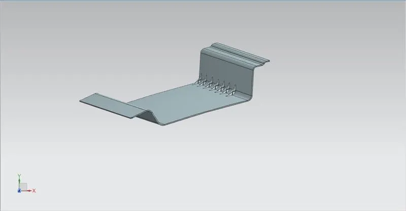
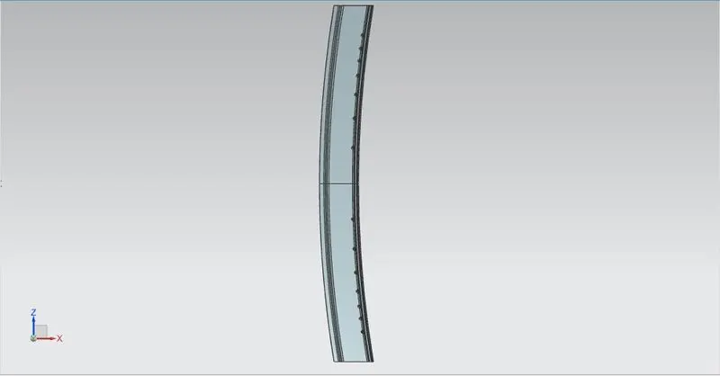
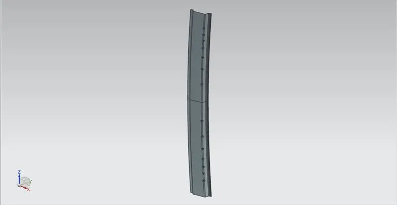
NOTE: The other roof rails are designed with the same procedure as the front roof rail. They are designed according to their master section and dimensions.
Center Roof Rail:
- Thickness: 1.5 mm
- Span: 60 mm
- Length: 1038.99 mm
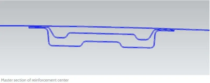
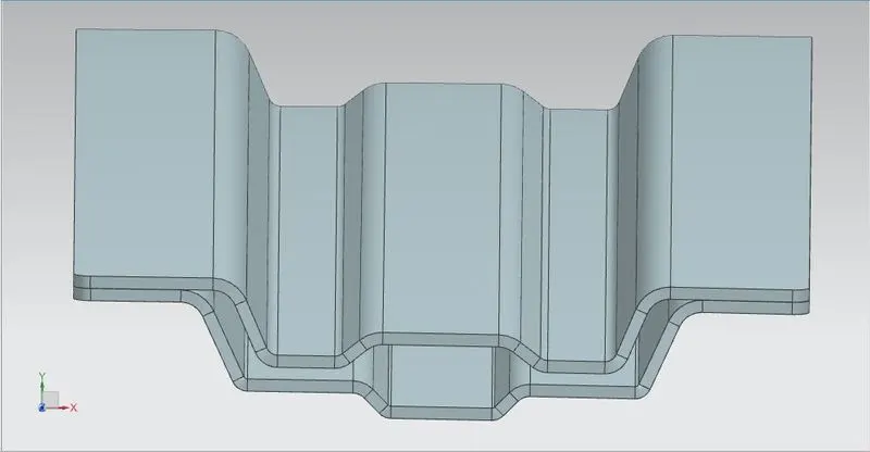
NOTE: The center roof rail can also have a re-enforcement center roof rail between roof and the center roof rail as shown in master section. This is used when it is not possible to place a bow roof before the center roof rail. Eg. If the roof has a sunroof.
This roof rail is made for supporting the center of the roof. This is attached to the B-Pillar of the car.
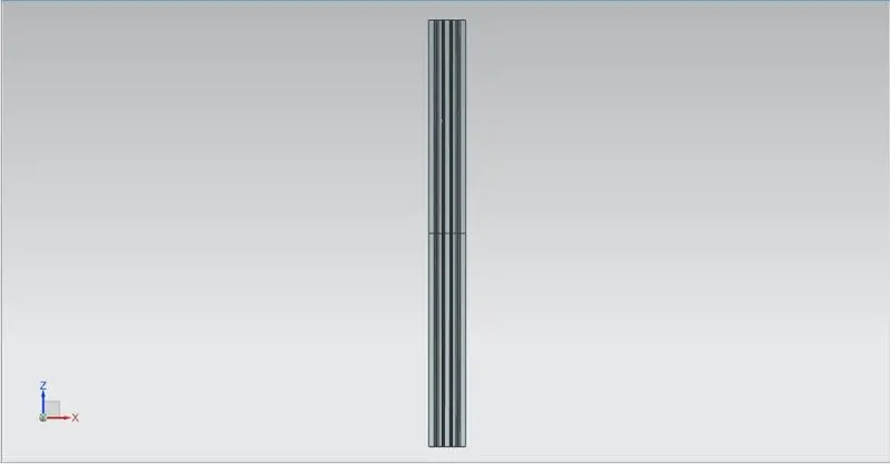
- The center roof rail is designed the smae way as the Front roof rail.
- It is designed according to the master section given.
- The span of the center roof rail is 90 mm
- The distance between the roof and the center roof rail is 5 mm to allow the mastic to be applied.
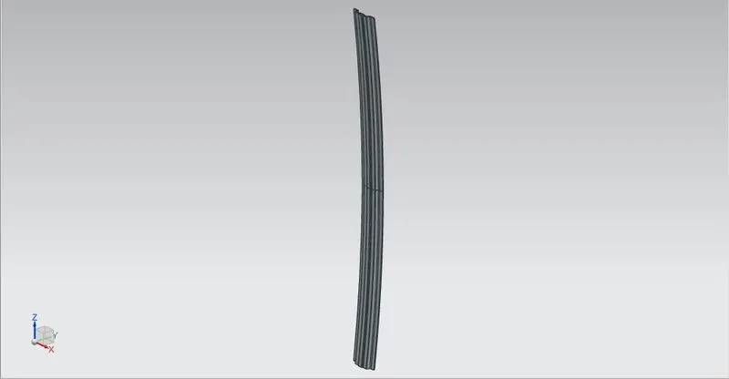
Rear Roof Rail:
- Thickness: 0.75 mm
- Span: 214.37 mm
- Length: 919.22 mm
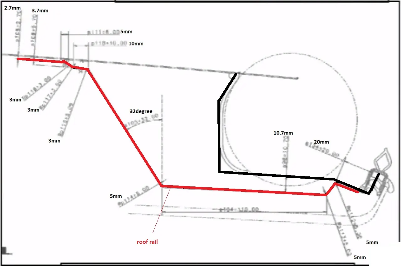
- Height: 100.7mm( assumed)
- The gap between the upper end of the rail and the roof is 2.7 mm
- This rail provides suppoet to the end of the roof
- The under part of the roof is 50 mm long
- Master Section:
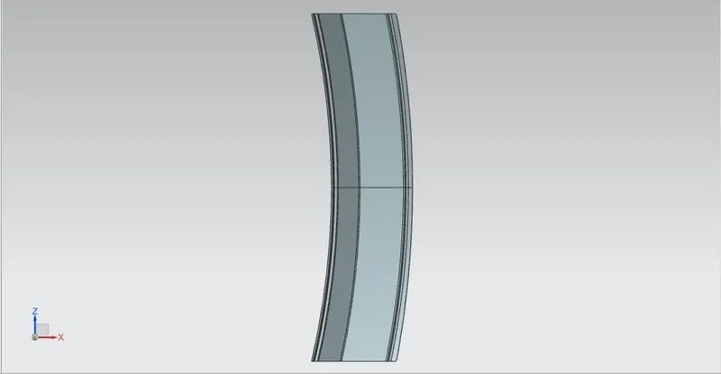
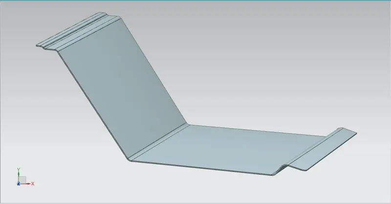
- Images:
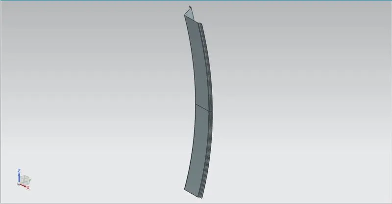
Bow Roofs 1 and 2:
Thickness: 1.5 mm
Span: 60 mm
Bow 1: 1038.99 mm
Bow 2: 989 mm
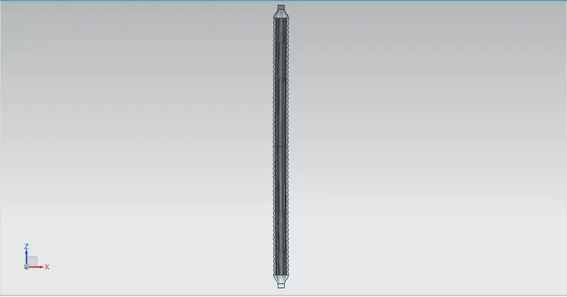
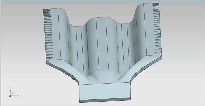
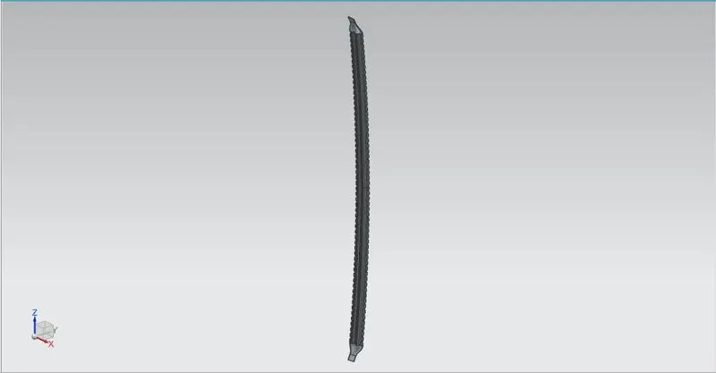
- Both the bow roofs are same in dimensions and design, except their lengths. Bow roof 1 is longer than bow roof 2 as the roof shrinks as it goes back.
- The bow roofs are provided if the roof is long and center roof rail is not enough to support the load of the roof.
- The bow roof is attaches with side flange to the roof.
- The bow roof is 5 mm below roof.
- The bow roof is attached via mastics to the roof.
- The bow roof consists of mastic points.
- The roof rail are attached by flanges to the roof. Through curve mesh command is used to make the surface between roof rail and the side flanges.
- Master Section:
- Images:
Heat Distortion Criteria:
This criteria is used to check wheather the roof deforms during high temperature. Eg. if the car is standing in sun for long time.
- To find the check the criteria a line is made by offset the center of the roof to 300 mm in X direction.
- The above line is then offested by 100 mm on both side
- A line is made in center of two concecative roof rails.
- Above lines are offsetd to 100 mm on both side
- The Intersection of all the line is projected on roof surface.
- An arc is draw in both X and Y direction. The curvature of the arc is measuread.
- Length of the roof is measured
- All the valuse are put in the formula below
Formula for heat distorsion criteria:
W = [1.73 x 10^(-3) x L] + [1.85 x 10^(-8) x (R^2)/t] + [ 1.10x10^(-3) x l] - 2.68
Judgement Condition : OK<2.7
Where
L = Roof Length in X-Direction[mm](Roof dimension in 0-Y)
R = Roof curvature
R = 2(Rx*Ry)/(Rx+Ry)
Rx = X curvature
Ry = Y curvature
t = Roof plate thickness [mm]
l = Bow Roof Span [mm]
Snow Load Criteria:
This is to determine wheather the roof will bear the weight of snow.
- To find the snow load, the center line is projected on a plane and the offseted by 100 mm on both side.
- The same procedure is followed as heat distortion.
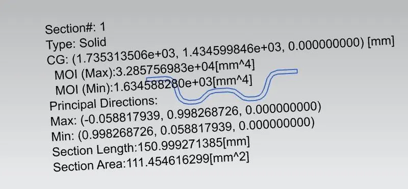
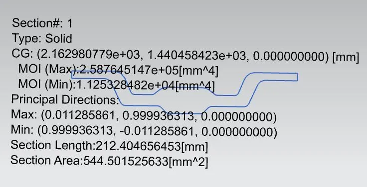
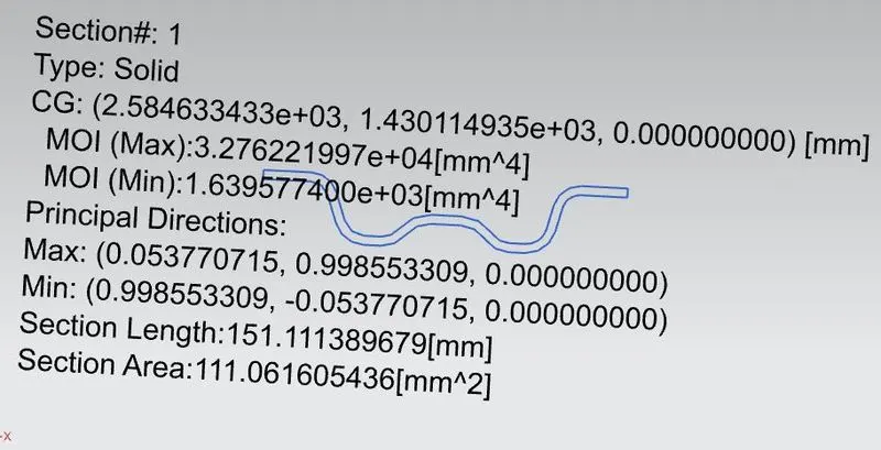
- Moment of inertia is measured of bow roof 1 and 2 and center roof rail
- length measure in y direction and indivisual length between the center of two consecutive rails along the x direction
- All the values are put in the formula to find the result.
Formula for snow load criteria:
Qr = [Iy x t2] / [α x s x [(Rx + Ry)/2]2 x 10-8]
α = My x Lx2 x 10-12 , My = Y(Ly-Y)
Judgement condition = Qr ≥ 3.1 and 250 ≤ s ≤ 380
t = Roof plate thickness [mm]
Ly = Distance between the front and rear roof Rails on the Vehicle along with 0Y[mm] Length of Roof panel with the center point between Roof rail Front /Rear as the reference point of the front and the rear.
Lx = Distance between the Left and Right end of the roof on the Roof BOW [mm] Width of the roof panel exposed on the surface.
Y = Distance front Front Roof Rail to Roof BOW[mm]
s = Distance for which Roof BOW bears divided load [mm]
Where, s = L1/2 + L2/2
Iy = Geometrical moment of inertia of Roof BOW (Y cross-section )[mm4]
Rx = Lateral direction curvature radius of roof panel Y cross-section on Roof BOW [mm] Roof panel curvature Radius of the Length Lx in Front view.
Ry = Longitudinal Direction curvature radius of the Roof panel X cross-section on Roof BOW [mm] Roof panel X curvature radius of length s in Side view.

Moment of Inetria:
- Bow Roof 1:
- Center Roof Rail:
- Bow Roof 2:
Assembly:
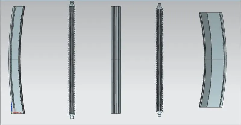
- All rails placement without the roof
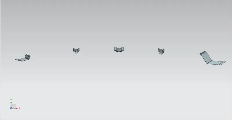
- Side View:
Draft analysis:
- Roof:

- Front Roof Rail:
- Center Roof Rail:
- Rear Roof Rail:
- Bow roof:
- With roof assembly and all rails: