REVIT_USAGE OF ELEMENTS AND PROPERTIES_WEEK 3
WEEK-3 CHALLENGE :
N.KEERTHANA
AIM : To understand how to insert elements and components from revit library to give details of our project and modify their properties according to the requirements of the project
INTRODUCTION : In this project we learn how to add elements and model components and make changes in their properties to meet the requirements of our model.
Here, I have used the project file created for week-2 (I.e, Residential model) and added the basic elements such as floor, roof and components such as furniture, lighting, plumbing fixtures and other speciality equipments required for residential building.
In this challenge, we majorly used modify tab and properties browser to add elements into the model.
- Adding Floor :
- Open a floor plan view
- Goto Architecture tab > Build panel > Floor > Floor architecture
- Select a type of floor from the properties browser
- We can draw the floor by the tools in modify tab such as pick line, line, rectangle etc,.
- Sketch the path of the floor by selecting boundary line option as shown in the picture and then finish it by selecting the finish option
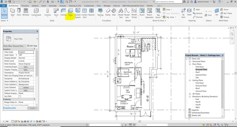
- Ground Floor plan view of the residential building
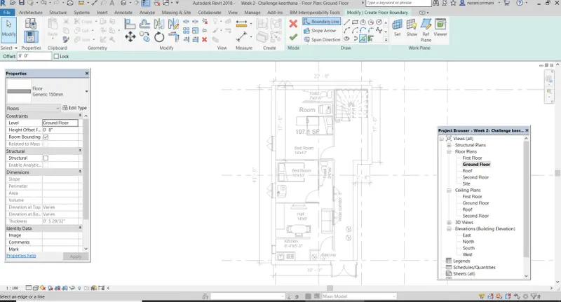
- Creating the floor
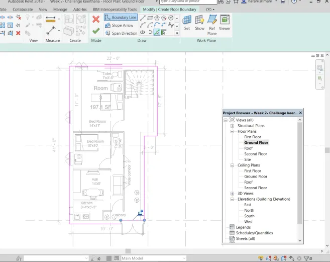
- Creating the floor by pick line method
- select the boundary lines of the building to draw the floor and the lines must form a closed loop to finish
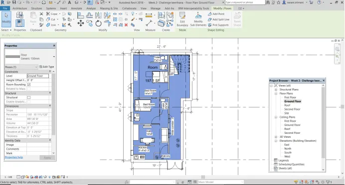
- Generic Floor is created and aligned with grids as shown.
- Modified the floor by changing the material and the properties of the floor as explained in the below pictures
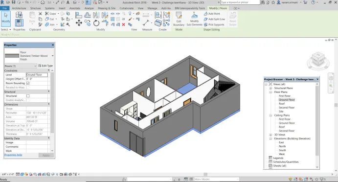
- Select the floor and click Edit type in properties browser
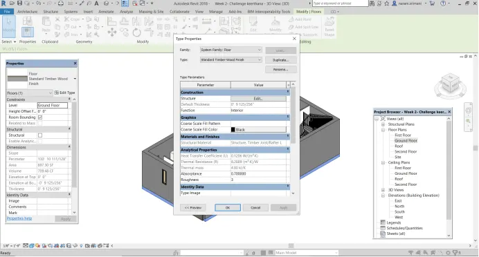
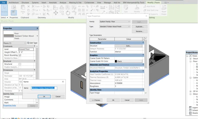
- Duplicate the element and rename
-Select Structure edit
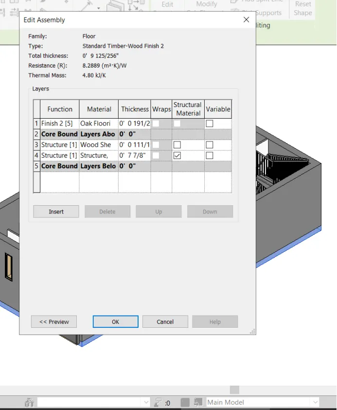
- Made changes in the thickness of the structure
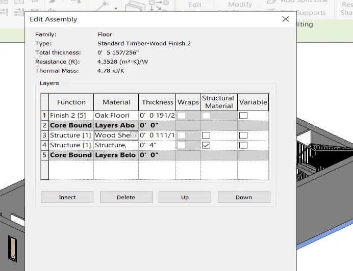
- To change the material, select the three dots beside the material in the structure function
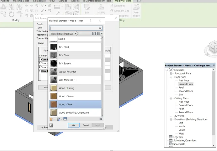
- Select an appropriate material for floor and click OK.
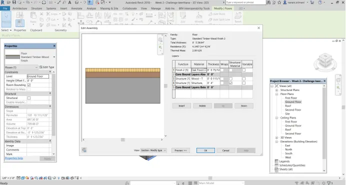
- We can see the preview by selecting the preview option as shown above and click OK.
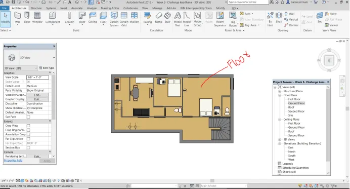
- The respective changes are made in the floor as shown in the above picture
- Adding Walls :
- Adding walls based on the floor layout: Goto Architecture tab>Build panel>Wall>Architecture wall
- Select a type of wall and in the properties browser, select the location line as Finish face exterior and select the base and top level as GFL and FFL respectively
- Use pick line option and select the boundaries of the floor that is created
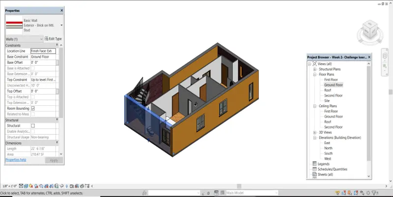
- Walls are created as shown
2(a). Based on my observation, connecting the walls with associated levels is beneficial than being unconnected
- If we change the height of the levels, the walls that are connected with that level also automatically changes accordingly, this is an advantage in making the wall connected with levels
- If we make the wall as unconnected, we have to again change the wall height and this may lead to some conflicts with the other elements attached to it
This can be explained by the following pictures -
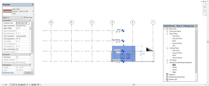

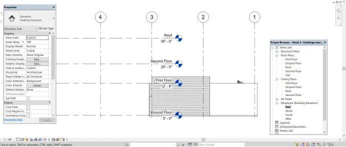
2(b). Modelling walls by height is more convenient than modelling by depth because we measure the height of the building from a base level and go in upward direction rather than doing it in reverse order. It is always convenient and beneficial to model bottom to top rather than modelling from top to bottom.
- Creating multi-level by using copy and paste options :
- To create multiple levels with the same elements and same layout, we use copy to clipboard option and then paste it aligned to different levels
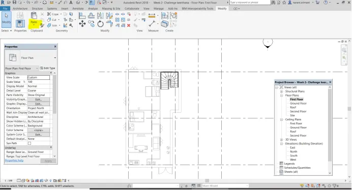
- Goto ground floor plan view and select the entire plan view of the model as shown and then select copy to clipboard tool in the modify tab
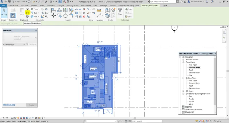
- Then, select paste from clipboard option and paste them aligned to first floor and second floor plans
- We can also filter the elements that are to be copied to other floors by using filter tool in modify tab
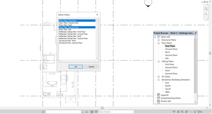
- Select the levels to which the elements are to be copied and click OK
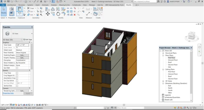
- All the selected elements are copied to the first and second floor levels
- We have created a multiple level residential building (G+2 Residential model)
- To add roof to the model, select roof in the architecture tab- build panel and select roof by Footprint
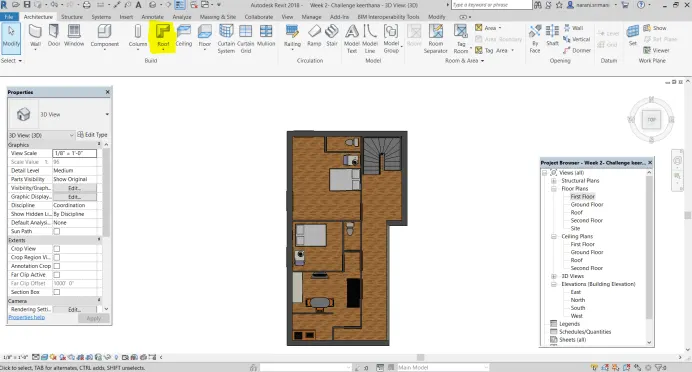
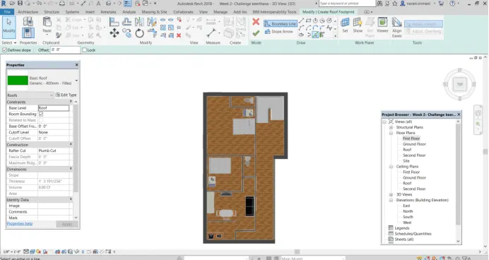
- Select pick line option and select the boundary lines to add roof
- set the base level as Roof (top level)
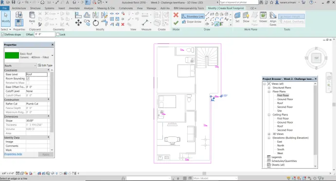
- Sketch the roof and finish
We can change the properties and material of the roof by selecting edit type in properties browser as explained from the pictures
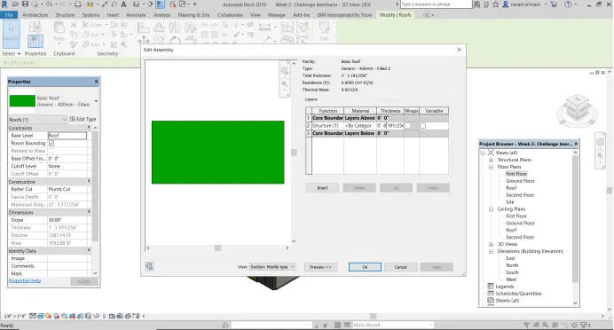
- Goto edit type and duplicate with a certain name and select Structure edit option
- We can change the thickness of the structure
- We can also change the material of the roof by selecting material option and then choose any appropriate material for the roof and click OK
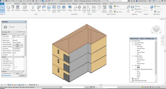
- The resulted roof structure is shown
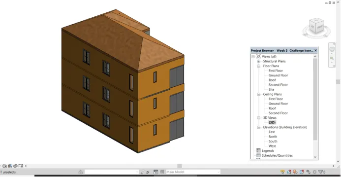
- Here is the realistic view of the model created
- To create interior partition walls to create separate rooms:
- Goto Architecture tab>build panel>Wall>Wall architecture
- Select the type of wall as interior partition wall draw the walls according to the dimensions required
- Here I have already drawn the interior walls in week 2 challenge, so I am continuing with that only
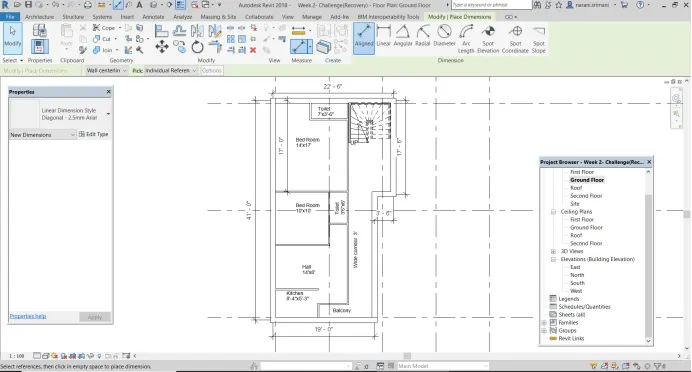
-We have created Rooms and also Annotated accordingly
- To place the components and give details to our residential model:
A). Placing doors and windows at appropriate locations
- Select the elements of doors or windows either from Architecture tab or from Revit library and place it accordingly in the walls
- Also, we can change the dimensions by editing the properties
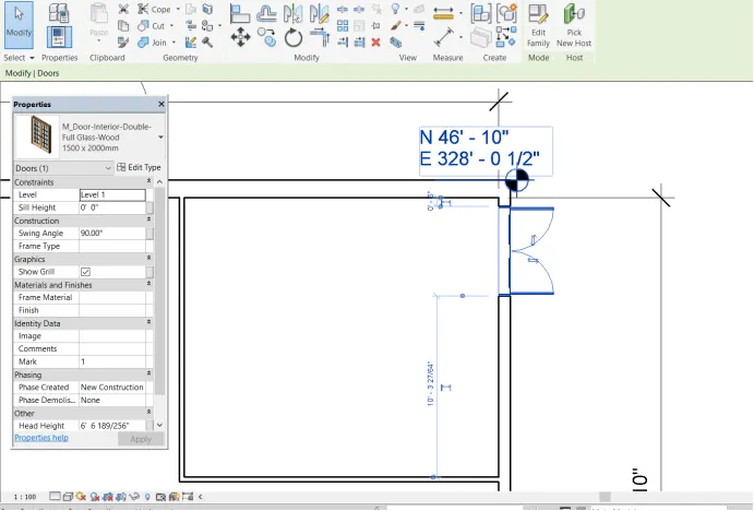
- Placement of window
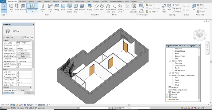
- Doors have been placed
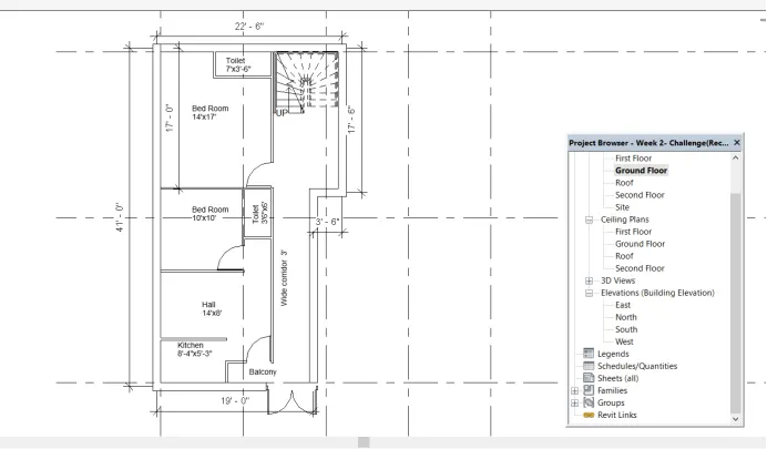
- A staircase also have been placed as shown
B). Placing of Furniture in different rooms
- To place a component, goto Architecture tab>Build panel>Component>Place a component
- Select Load family option in the modify| place a component toolbar
- We will be directed to the Revit library where all the components required for modelling are available
- Select a Category (eg. Furniture), select a family of that category(eg. Seating) and select an element of that family(eg. Sofa) and click open
- Place the component in appropriate place and adjust the dimensions accordingly
Various components have been placed for giving details to the model and adjusted to the requirements
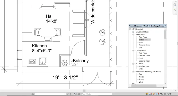
- Ground floor plan view of Kitchen and Living room/Hall
- 3D VIEWS :
- The 3D views (Camera views) of different rooms is shown below along with the components placed
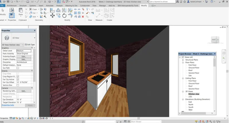
-3D VIEW OF KITCHEN ROOM
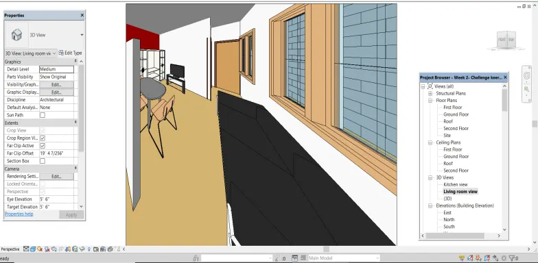
- 3D VIEW OF LIVING ROOM with attached dining space (camera view)
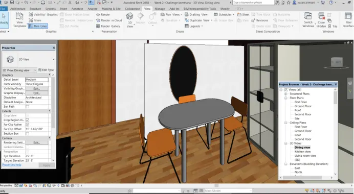
- 3D VIEW OF DINING SPACE
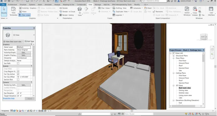
- 3D VIEW OF BED ROOM (with necessary components and furniture)
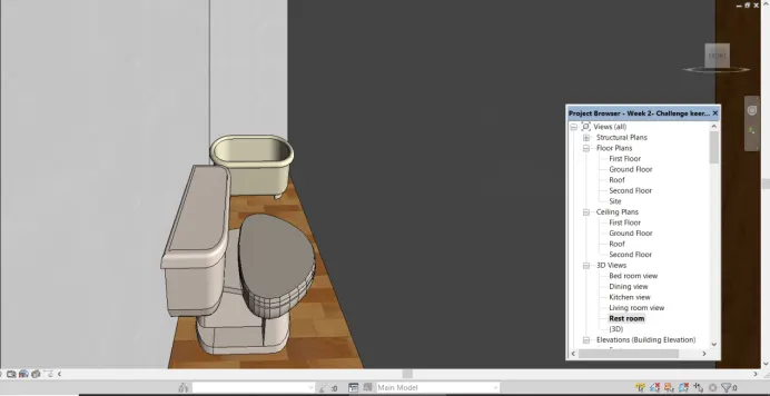
- 3D VIEW OF REST ROOM (with plumbing fixture and a bath tub)
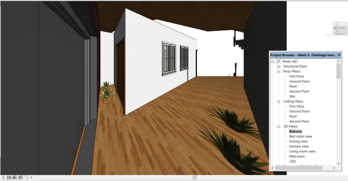
- 3D VIEW OF BALCONY (with some small shrubs placed along the wall)
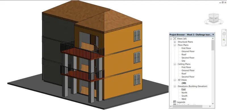
- Also placed balcony in first floor and second floor and added railings and columns to support
- RESULTS:
- Floors and roof are created and the properties are modified
- Walls are created and modified the material and structure of wall
- Various elements/components are placed in respective locations in different rooms
- A basic 3D model of G+2 Residential building is created with basic features
THANK YOU