REVIT_3D Rendering of a House plan_Project 1
REVIT_3D Rendering of a House Plan_Project1:
PROJECT BY - N.KEERTHANA
AIM : To present the 3D Rendering of a House plan and also to add details to the project and present the project in the form of sheets.
INTRODUCTION : In this challenge we create different Rendering views of different rooms from the project created in week 3. We learn how to work as a group to make the project detailed. We divide the model into Architecture and Structure categories such as creating architecture plans and structural plans and add details accordingly. We make the project detailed by adding details to project such as annotations, adding plan views, section views, creating sheets and adding all views to the sheets to create brief report of the project. In this project we focus more on drafting and designing standards to make the project as detailed as possible.
1) Based on the project saved from Week 3, proceed from First Floor Level .Model a Ceiling from architecture tab above the walls at first floor level
To the project saved from week 3, proceed from First floor level by adding Ceiling above the walls as mentioned in the following steps:
- To create ceiling goto Architecture tab > Build panel > Ceiling
- Select sketch ceiling and draw the path of ceiling and finish
- Also can change material and type of the ceiling from the properties browser
- We can either select the level of the ceiling as First floor with no height offset or select the level as Ground floor and keep the height offset accordingly from the level as shown in the pictures
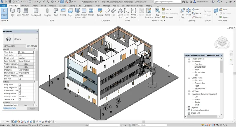
- Building model saved from week 3
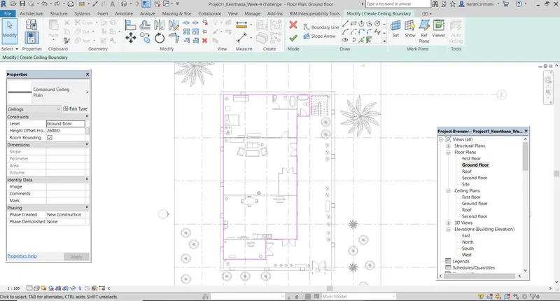
- Sketching of ceiling by selecting boundary line
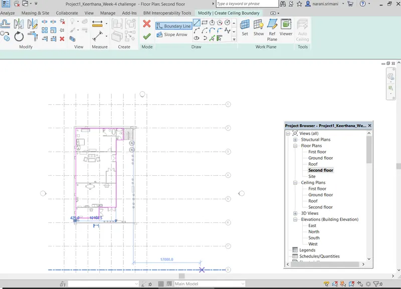
- Created ceiling for first and second floors also
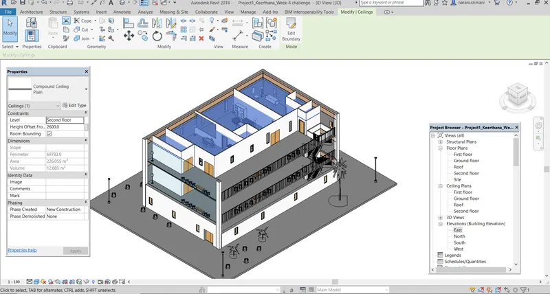
- Modelled ceiling for the GF, FF and SF as shown in above picture
2) Model a roof above the ceiling by selecting the footprints of ceiling. Using the adjustment tool bars appearing on screen adjust the roof slope to 10 degrees
To model roof above the ceiling by the footprints of ceiling and adjusting the roof slope as 10 degrees by following the steps below:
- To model a roof goto Architecture tab > Build panel > Roof
- Select Roof by footprints
- Select the level as roof level and then select the path by selecting the boundary by pick line method

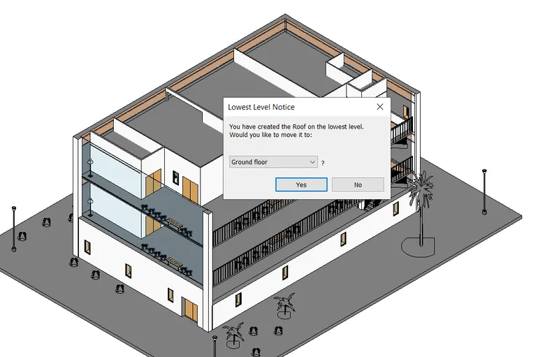
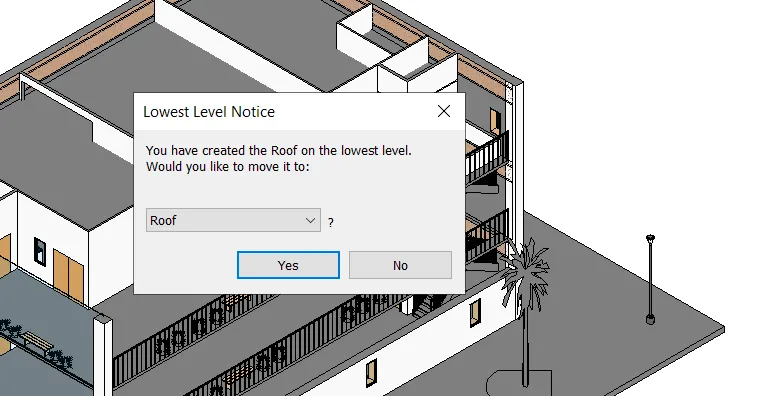
- Select roof level and click yes
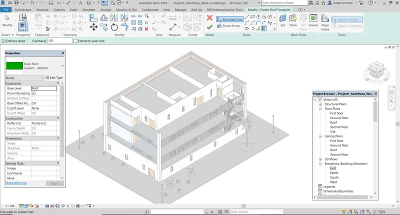
- Then select pick line option to sketch the boundary of roof
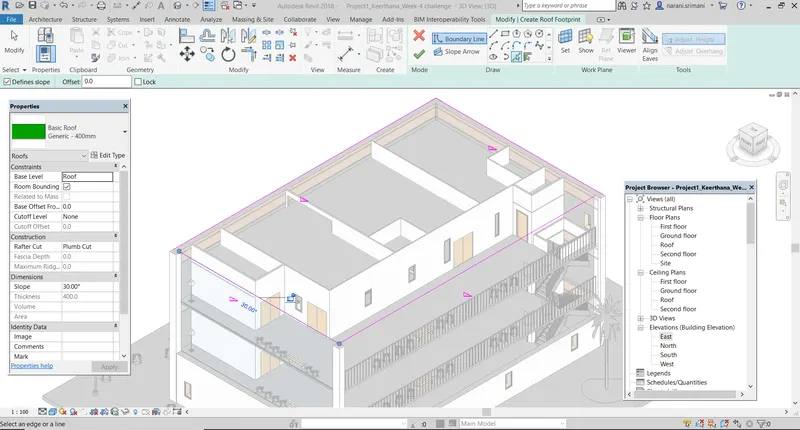
- After sketching, finish the sketch
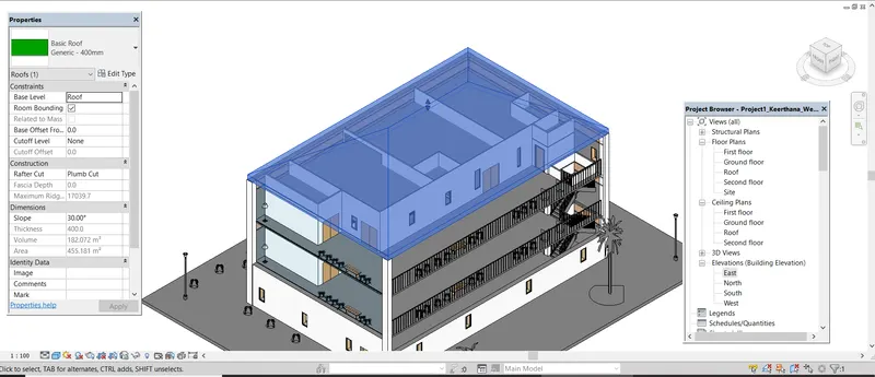
- Roof will be created as shown
- Now, adjust the slope of roof by the arrows displayed on the roof
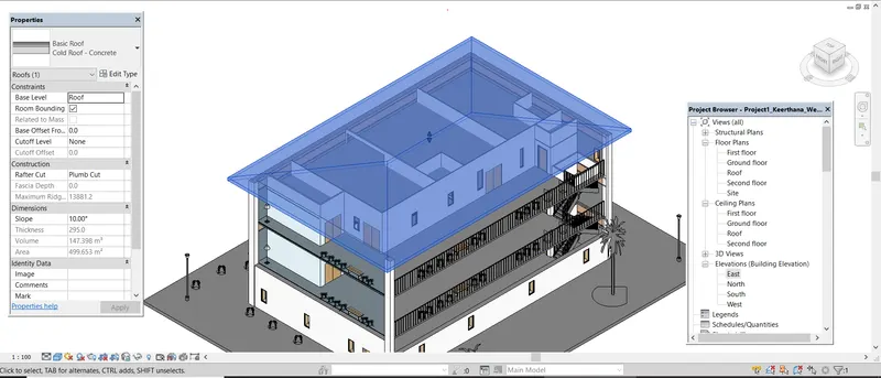
- Adjusted the roof slope to 10 degrees as given in the question
- Extended the roof outwards in all directions by a little amount
3) Using the file saved from week 2 to 4, create plan views for ground floor level and first floor level including all the walls , floors and components. Separate them to
architecture and structural plans
a. Architecture plan must have walls , floors and all the components placed within the building
b. Structure plan must have details of only walls, floors and columns
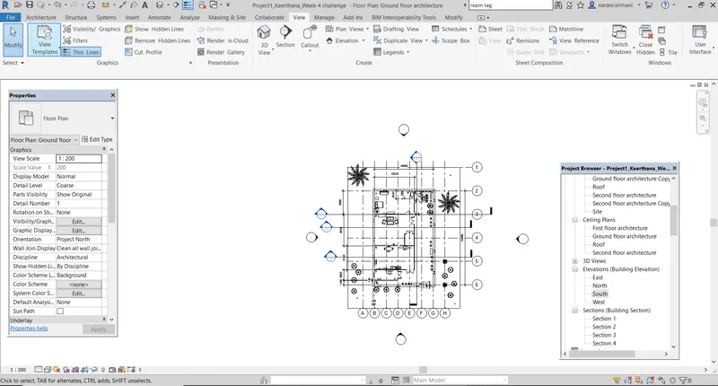
- To create the plan views, goto View tab > Create panel > Plan views
- Select the type of plan view and select the level of plan view
- Create Structural plan views and Architectural plan views and name them accordingly as explained in below pictures

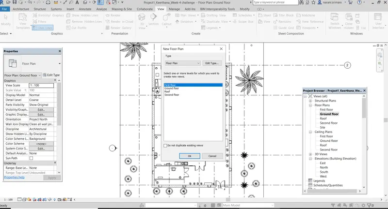
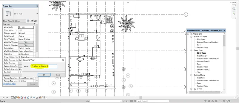
- Renaming the views created
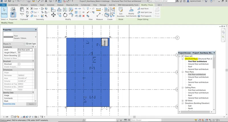
- Created Structural plan views
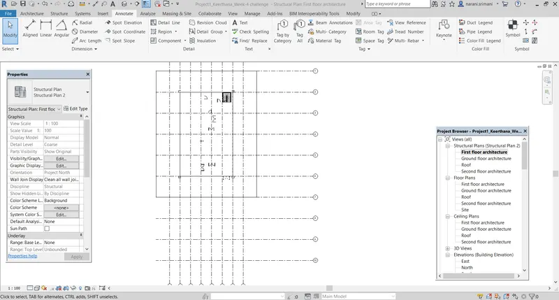
4) Using annotate tool bar add dimensions to all the walls and floors with reference to the longitudinal and transverse grids created in the project file
a. The architecture plan dimensions include details on where the components are placed within the buildings with relation to grids. Overall dimensions are sufficient for architecture plans
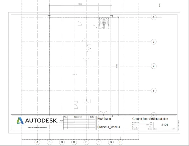
b. The Structure plan dimensions must include details on position of all the walls and interior walls with reference to grids. Locate all the framing components of the building with reference to a fixed point using Structural plans
- To Annotate the model created goto respective views and then annotate
- Goto Annotate tab> Dimension panel>Aligned
- We can also add spot elevation, Spot slope, spot coordinates, angular dimensions, etc., by selecting the respective icons/options in dimension panel as shown in below pictures
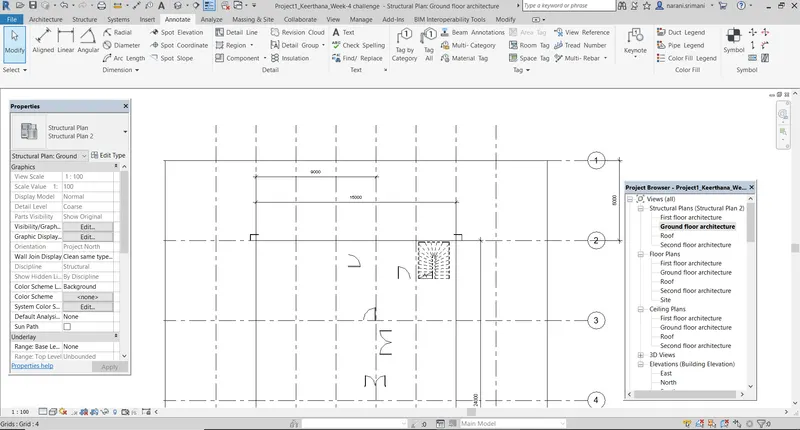
- Structural plan view with dimensions of walls
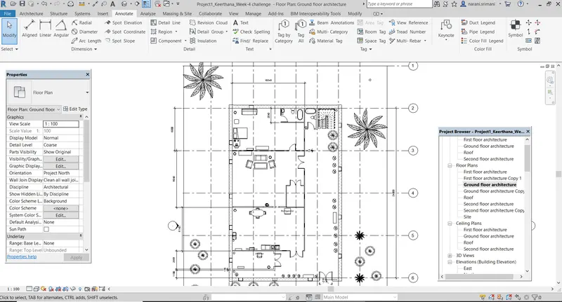
- Architectural plan - GFL
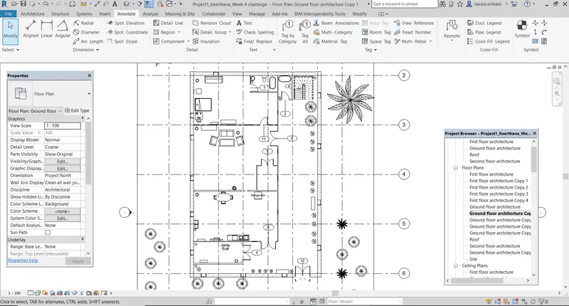
- Architectural plan - GFL with Door tags
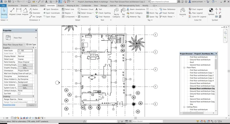
- GFL Architecture plan with Window tags
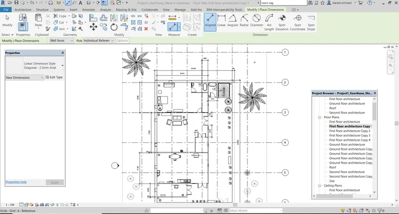
- FFL Arrchitecture plan with dimensions with respect to grids
5) Create a sheet template from the view tab and adjust the parameters on the sheet to add appropriate views
- To create sheet template goto View tab> Sheet composition panel > Sheet

- A new sheet window opens
- Load the sheets by selecting load icon
- It will navigate to the revit library, goto titleblocks and select the appropriate sheet
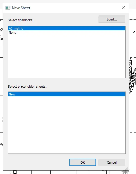
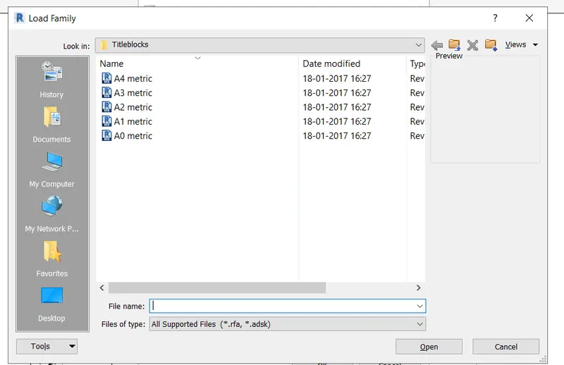
- select respective sheet such as A3 metric and click open
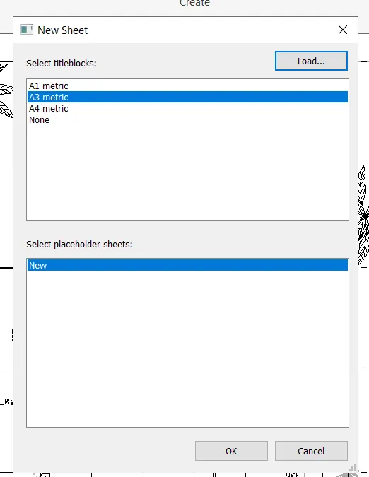
- Now, click ok.
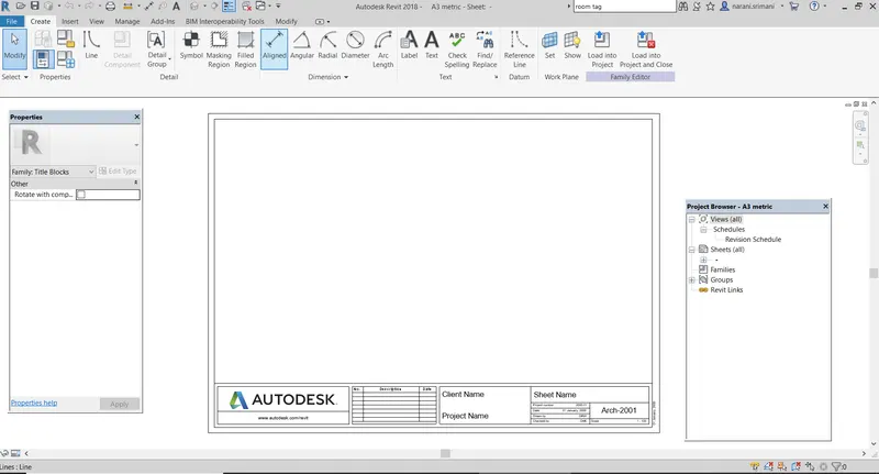
- The selected sized sheet template appears
- We can make changes in the sheet template such as the logo, the titles, owner name, project name, etc.,
- After the changes made select the LOAD INTO PROJECT icon to load the sheet into our project
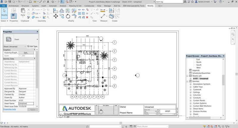
- Now we can add the created views like GFL, FFL, SFL plan views and name them accordingly
- We can change the details in the sheets like Sheet name and number, project issued date, description, etc.,
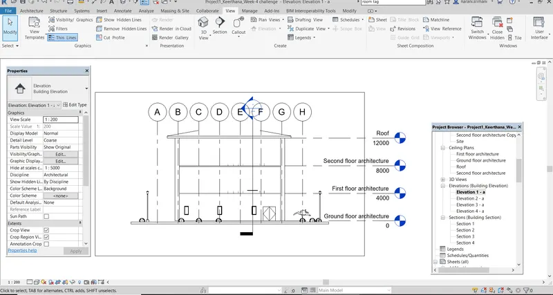
6) Using the elevation tab create the elevation views, looking at your building from East, North, South and West
- To create elevation views of the building from East, North, South and West - goto View tab>create panel>Elevation tool
- Select any type of elevation icon and add the elevations in four directions as shown below

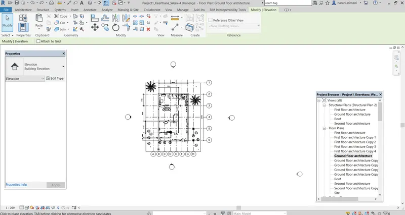
- Added the elevation views to the building
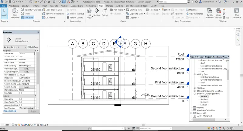
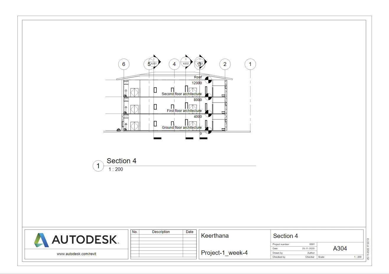
7) Produce section cut through each room either cutting across longitudinally or in a transverse direction
- To add section cuts, goto View tab>Create panel>Section tool
- Add the section cuts either accross longitudinally or in a transverse direction through each room and adjust accordingly

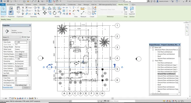
- Adding the section views
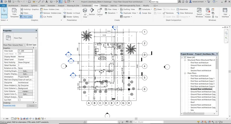
- Added the section cuts as shown in the pictures
8) Classify the views , Plan Views, Section Views and Elevation views to either Design or Documentation category using Properties browser
- To classify the views to either Design or Documentation category, edit the properties in the properties browser
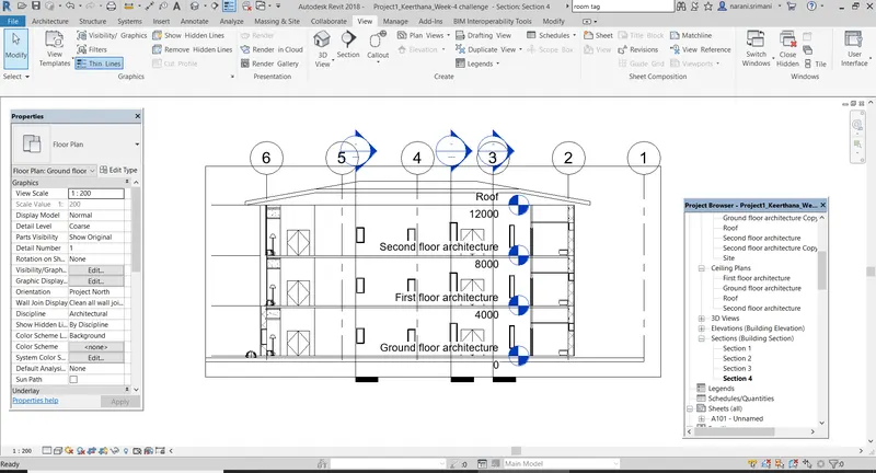
9) Using the sheet template produced create multiple sheets as follows
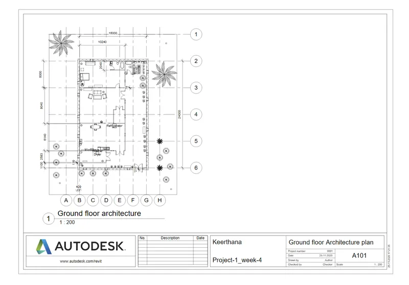
a. A 101 – Ground Floor Architecture Plan
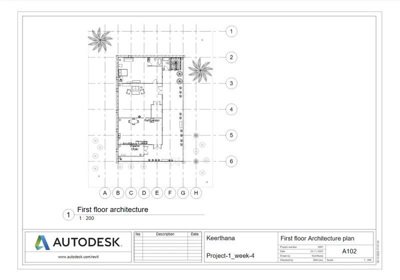
b. A 102- First Floor Architecture Plan
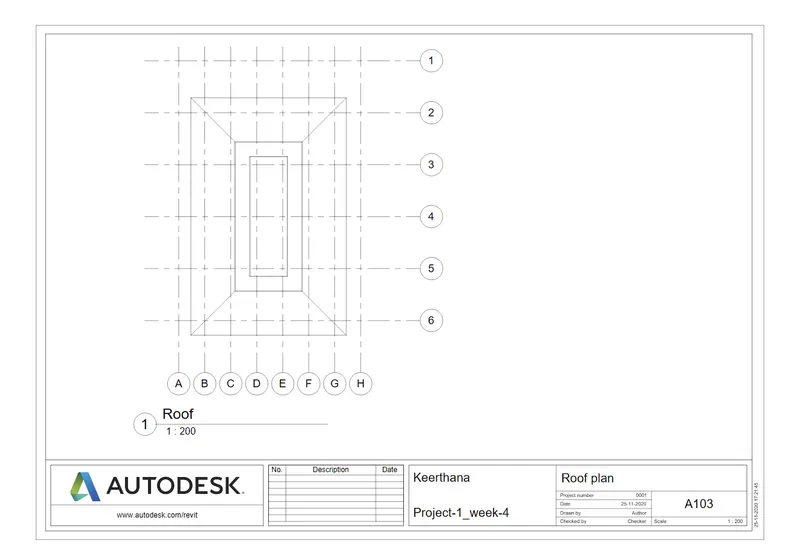
c. A 103- Roof Plan
d. S 101- Ground Floor Structural Plan
e. S 102 – First Floor Structural Plan
f. S 103- Roof Framing Plan
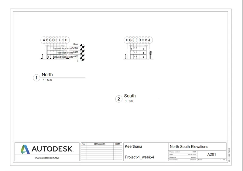
g. A-201 – North South Elevations
h. A-202- East West Elevations
Add additional sheets based on the sections created in your revit file
- To create multiple sheets using the sheet template created
- Goto Sheets in Project browser, right click on it and select new
- Rename it accordingly and give the sheet name
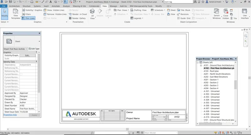
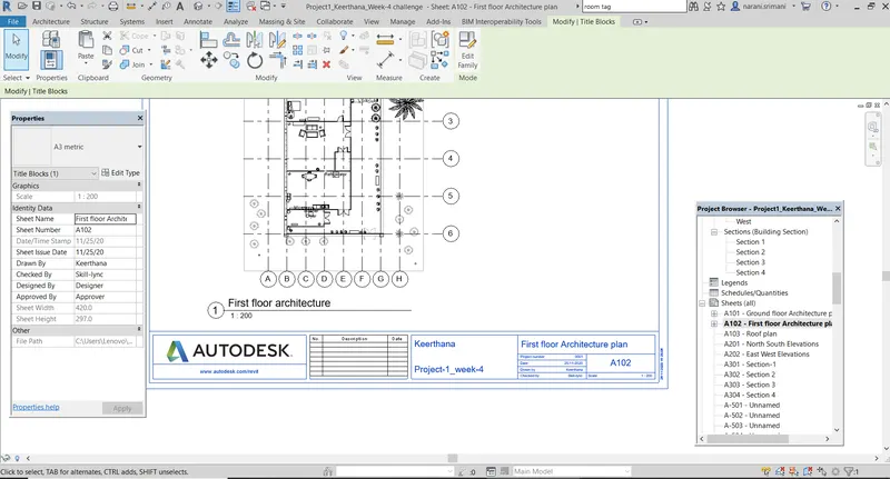
- Renaming the details of the sheet and adding the views to sheets
- To add any view to the sheets, open the sheet and drag the view into the sheet and adjust the scale of the viewto fit into the sheet
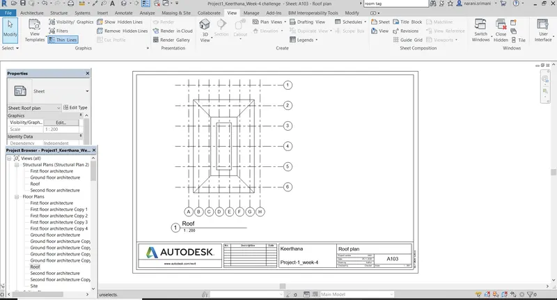
- Sheet consiting of ROOF plan
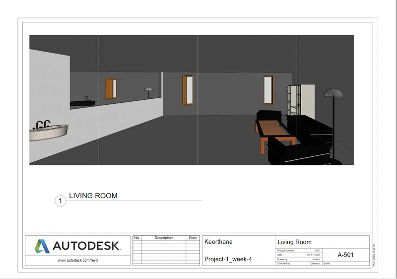
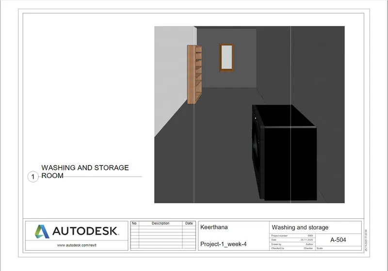
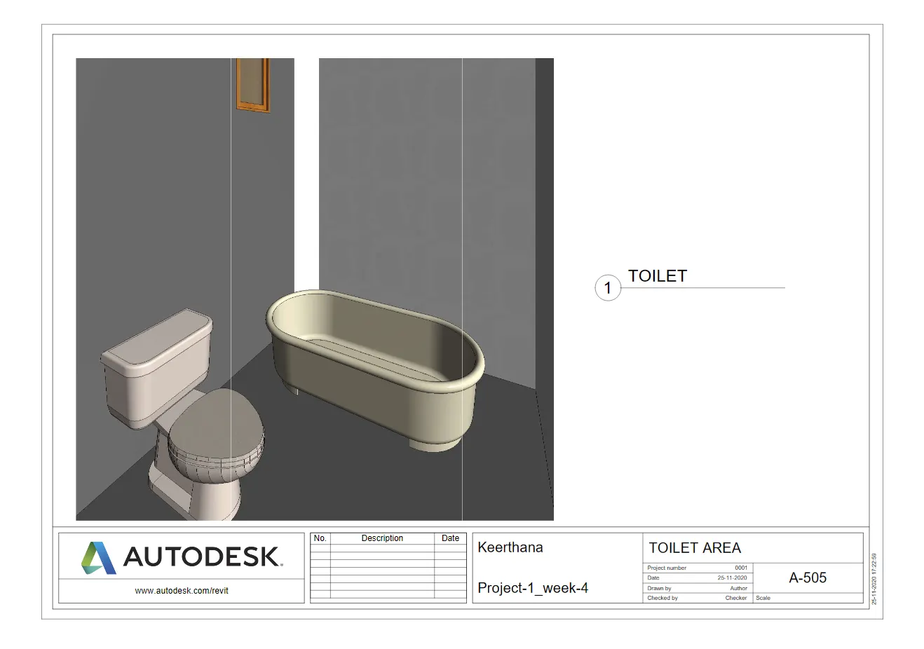
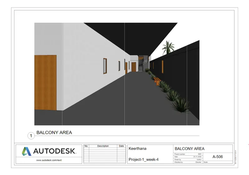
10) Create a camera specific view or a 3D view in each room ( living, dining, bed room ) . Based on the views create new shet of sheets starting A-501 (you can add as many sheets after , 502, 503.. n)to place the 3D view images.Produce the sheets as a part of project drafting.
- To create camera view or a 3D view, Goto View tab> Create panel> select either 3D view or Camera view
- For camera view, place the camera appropriately so that the realistic camera view of the selected portion will be created
- We can also render the camera views and 3D views, for that goto View tab> Presentation panel> RENDER
- Select the region to render
- In the Rendering dailog box, select the required settings such as Quality, Lighting, Background style
- Then click on Render icon, it will take sometime to render the selected region
- Rendered view according to our settings will be created
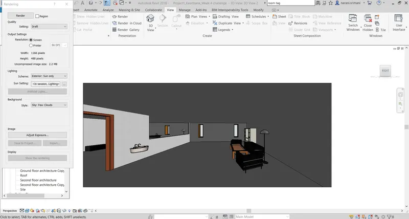
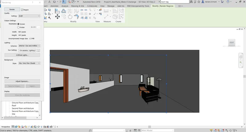
- SHEETS :
Various sheets are created for the different views and all the views are inserted into the sheets accordingly
- PLAN VIEWS
- ELEVATION VIEWS
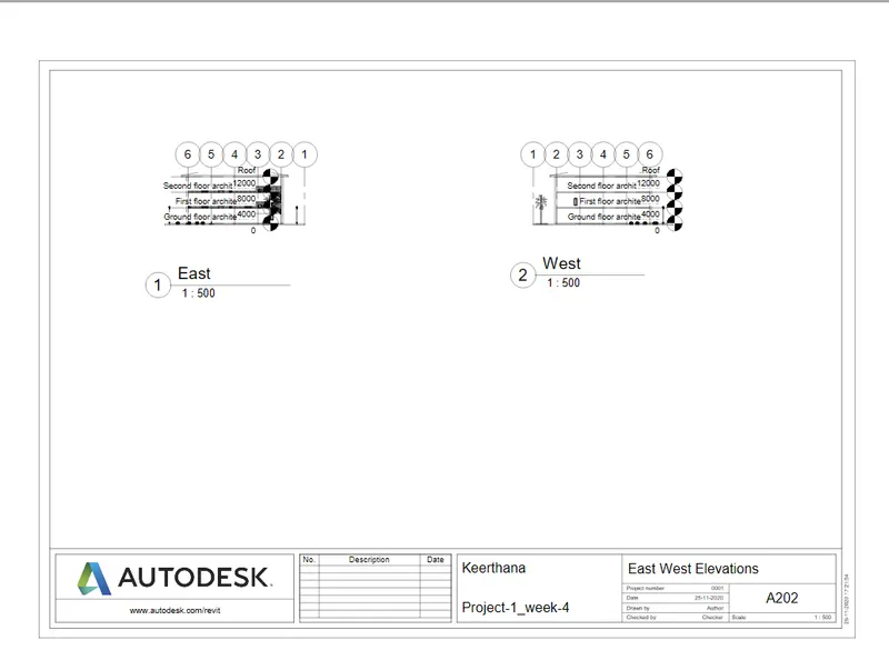
- SECTION VIEWS
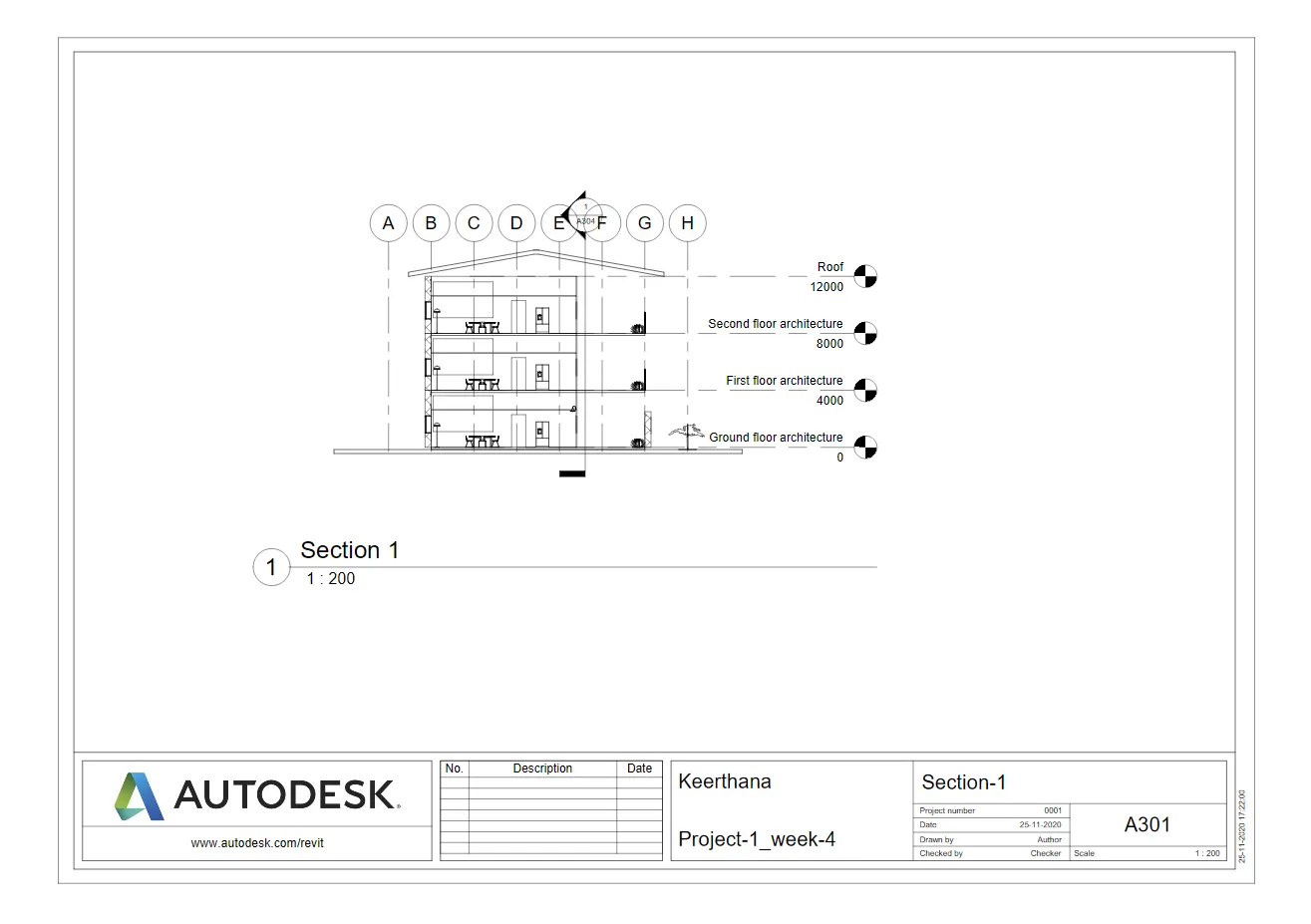
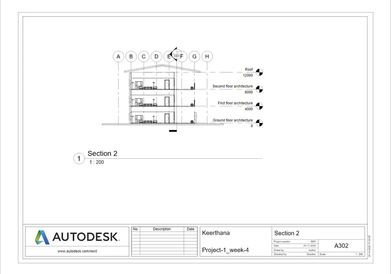
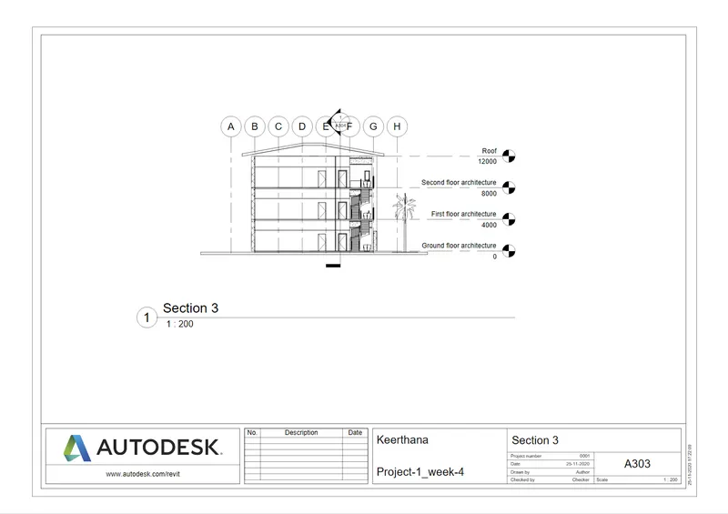
- CAMERA VIEWS OF DIFFERENT ROOMS IN THE BUILDING
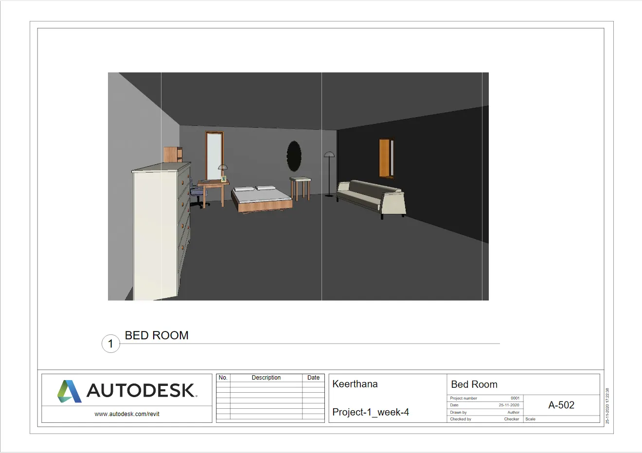
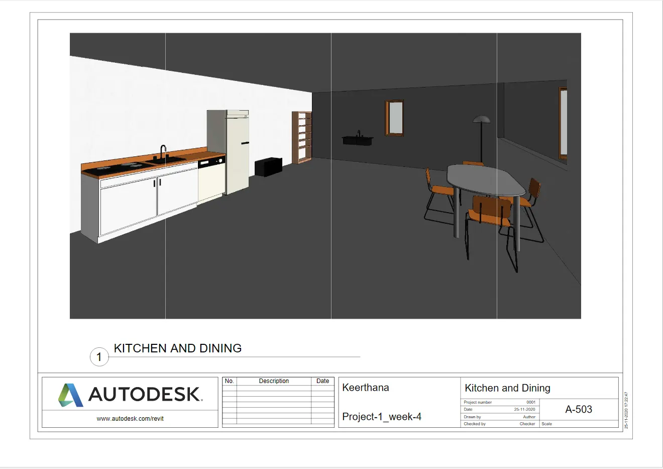
- STRUCTURAL PLANS
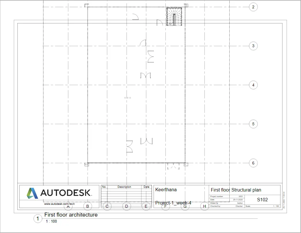
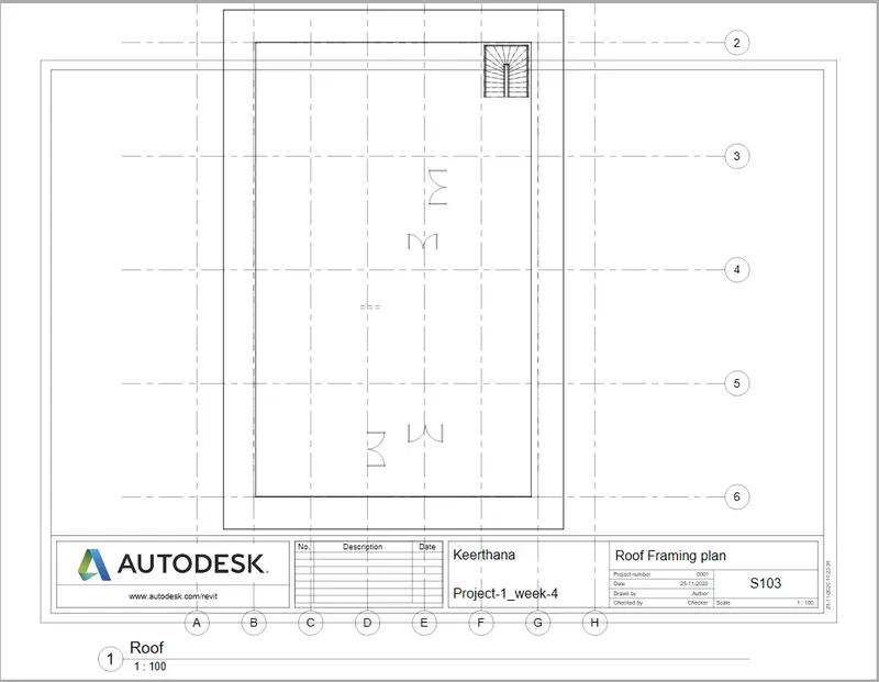
- 3D VIEW OF THE MODEL
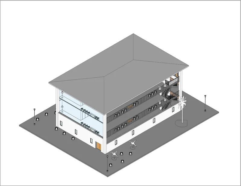
RESULTS :
- Created ceilings at first floor, second floor, roof levels
- Modelled Roof on the top of the building
- Created plan views and seperated them into Architectural and Structural plans
- Annotated the plan views accordingly
- Created Sheet template and modified the parameters on it
- Added Elevation views and Section views
- Created multiple sheets and added the views accordingly
- Created Camera views of different rooms and included in the sheets for presentation
THANK YOU
- N.Keerthana