REVIT_ Plan, 3D View & Structural Drawings_Project 2
1) Select the type of structure you want to build from one of the three below
a. Multi Unit Residential Apartment
b. Office Buildings
c. School
Ans: The type of structure I want to build is Multi Unit Residential Apartment.
2) Assume reasonable assumptions for geographic and location details for your project modeling. Based on assumptions and type of structure selected identify the modeling requirements from NBC
Ans: The following are assumptions I made for geographic and location details for my residential building:-
- The bulding area is situated in an averagely populated area with buldings in 3 sides and road on remaining side.
- The road is about 3 meters width.
- It is located in Habsiguda with pincode 500007 in Hyderabad i.e., a plateau area.
Model requirements from NBC :
- The offset on side where road is there is to taken atleast 4m as the bulding to be constructed is an apartment.
- In the other 3 sides of building, leave atleast 3m for vehicle movement.
- The height of bulding shouldnot be more than 50 feet
- Filling and cutting can be calculated in revit software.
3) Using the structural model, include the following components based on the type of structure selected
a. Foundation – Isolated / Wall/Matt Foundation
b. Columns
c. Beams Connected to Columns
d. Roof Framing/ Truss
e. Floor / Decks
f. Floor Openings for Elevators and Stairs
AIM : To include the components mentioned above for residential apartment in structural revit file.
TOOLS USED: Architecture, Structure,Property, Columns, Foundations, Beams, Roof, Floor, Shafts.
PROCEDURE :
1. Open the structural model that we created previously.
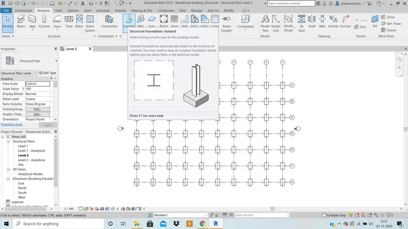
2. In the structure menu, click on foundation tool and select type of foundation as required( i choosed isolated) and place foundation on each grid intersection and important thing is that we need to create foundation in foundation level whcih is to be created under ground level.
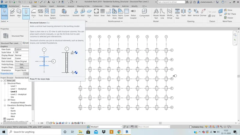
3. To place columns, select the column tool in structure menu and place columns on each foundation .
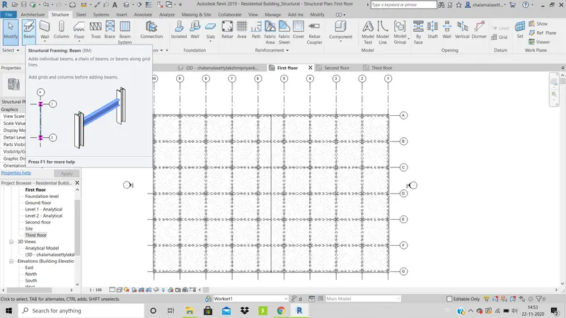
4. Now using beams tool and select type of beam required using property drop down and connect all the columns to create beams both longitudinally and transversly.
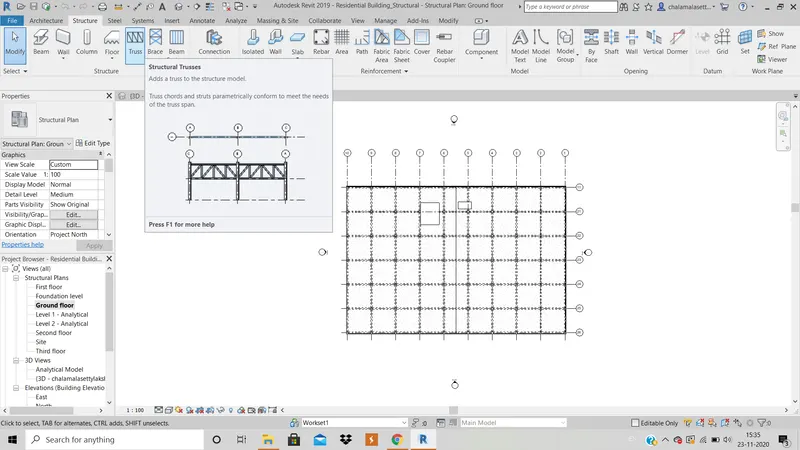
5. Roof wont be visible as it is architectural component so we can create a roof framing using the roof framing tool in structure menu or we can use truss tool in structure menu as required ( here i am not creating any kind of truss or roof framing as is i dont require them for my model.)
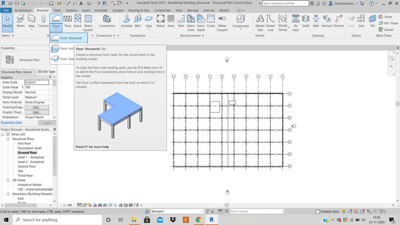
6. Using floor tool we can set boundaries and create floors.
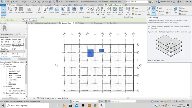
7. Click on shaft in architecture menu, and set boundary wherever shaft opening is required for staircase or elevator.
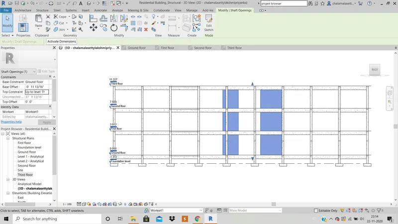
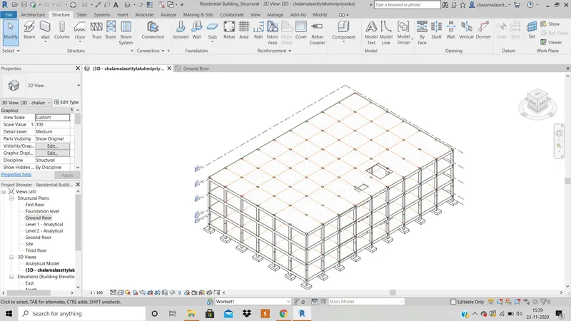
RESULT : The model obtained by doing all the above operations is shown below :
4) Using the architectural model, include the following components based on the type of structure selected
a. Wall Layout with appropriate material and finishing
b. Exterior façade with fancy finish
c. Interior partition walls to size rooms
d. Components to add details to room ( Desk, Chair, Lighting, Plumbing fixtures)
e. Add components such as stairs Elevators
f. Have at-least one side of building with curtain walls and glass panels
g. Include interior and exterior lighting fixtures
h. Place proper topographic components from outside ( Trees, Parking, Plants) to add details to the model
AIM : To include the above mentioned components based on type of structure selected in architectural file.
TOOLS USED : Architecture, Wall, Curtain walls, Property, Load family, insert tab, components, Staircase.
PROCEDURE :
1. Now, open architecture file of the residential building.
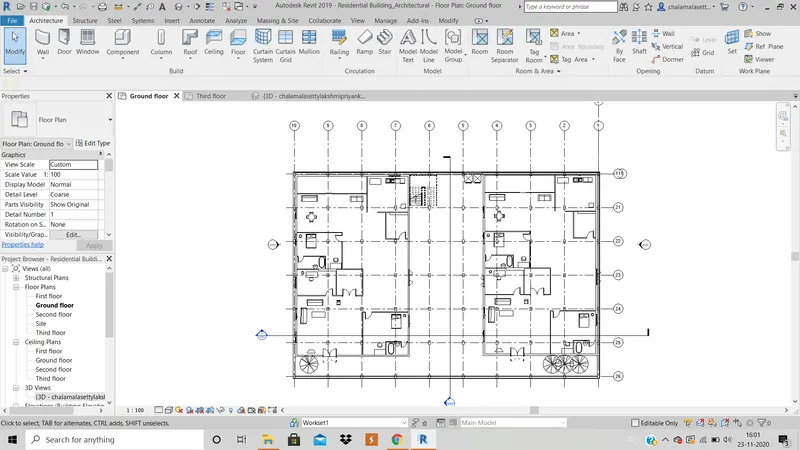
2. Select wall tool in architecture menu and design a plan as required for plan.
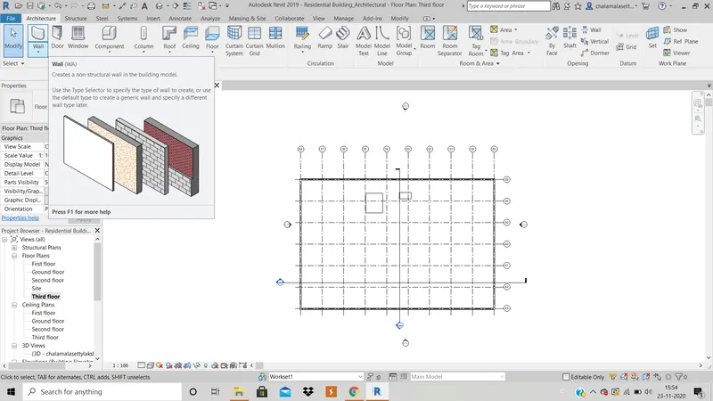
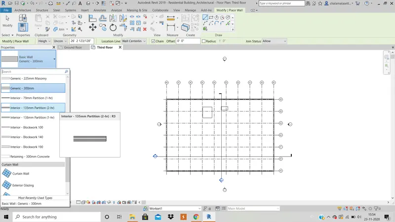
3. Select wall command and in property tab, choose type of wall required such as interior partition wall and design the interior part of building.
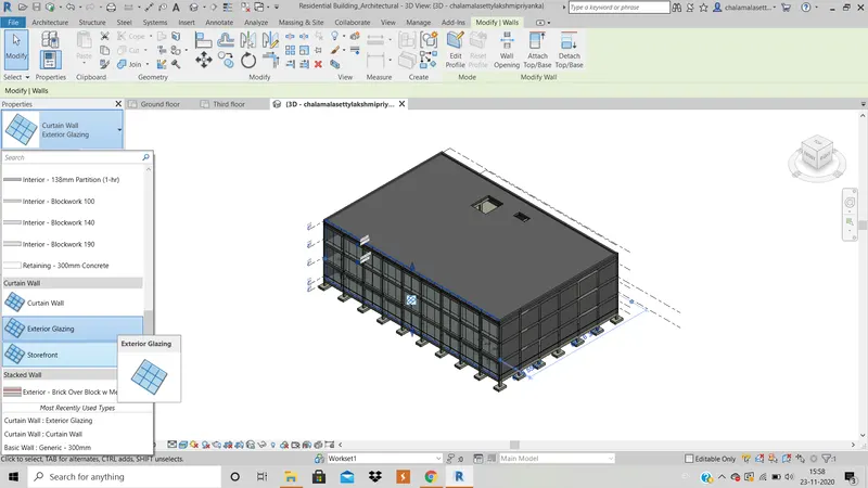
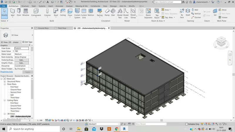
4. In the architecture tab, click in curtain wall and select the wall to be of this type.( Though it does not suite for the building i have choosen , i have made one wall as curtain wall as asked in question).
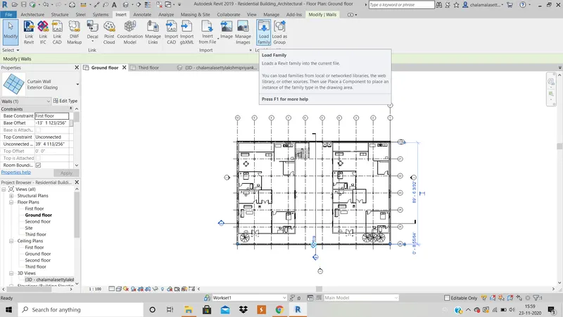
5. In the insert tab, click on load family and go to indian and choose the components required.
6. In the architecture tab, click on components and select the required loaded component and plac eit in the building where ever required.
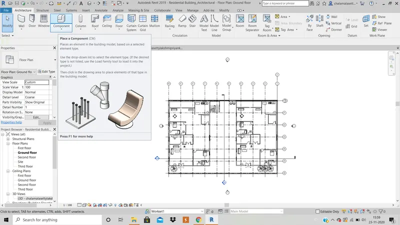
RESULT : The model obatianed by performing above operations is shown below :
5) Provide set of drawings in architectural and structural model to list the following details with categories and appropriate sheet templates included
a. Floor Plans with Annotations
b. Elevations
c. Sections
AIM : To create sheets for floor plans, elevations and sections.
TOOLS UESD : View tab, sheets, view, section
PROCEDURE :
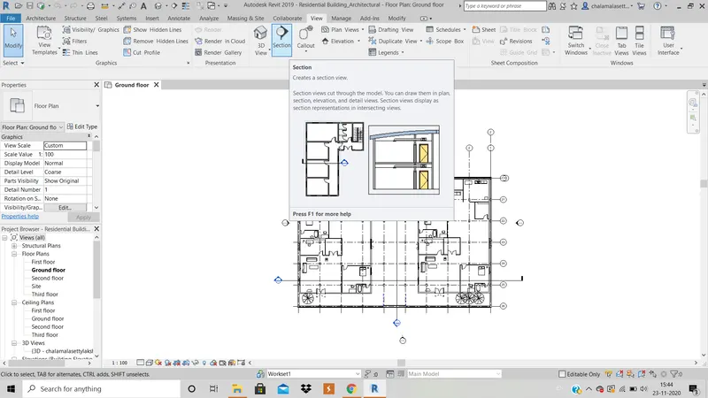
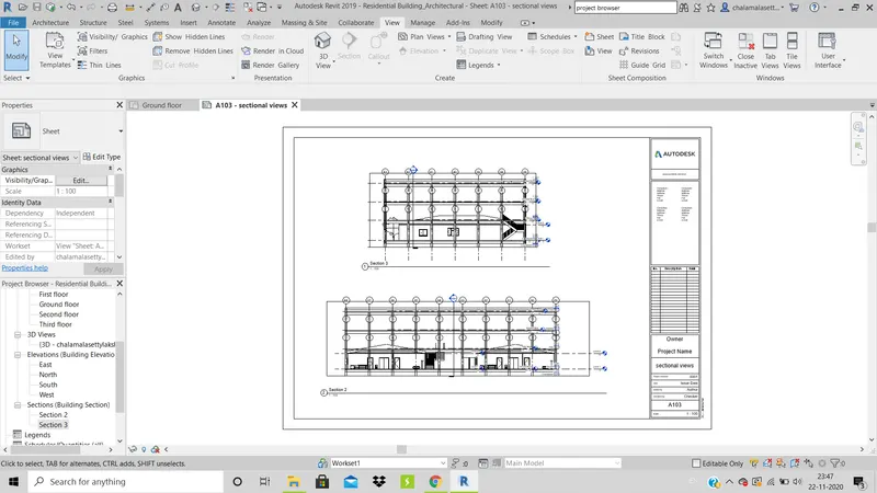
1. In the view tab, click on section tool and draw the sectional line in plan to create the required section.
2. Click on sheets tool in view tab and select A1 metric sheet and click ok.
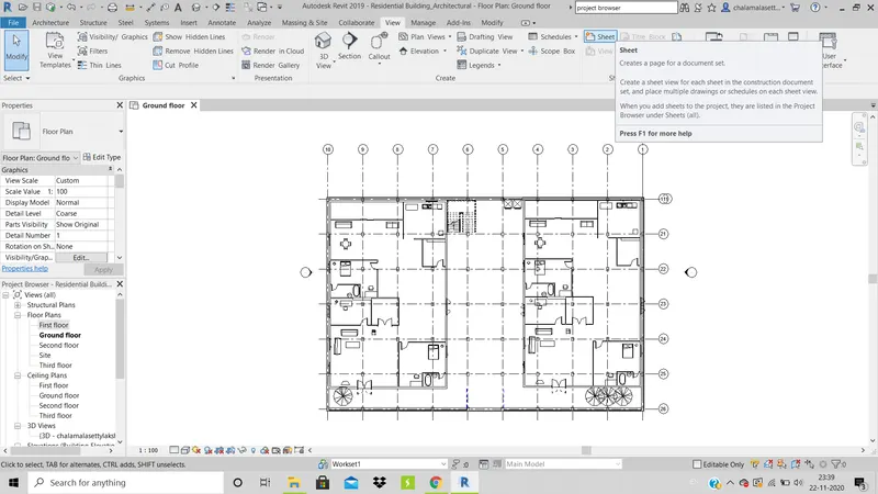
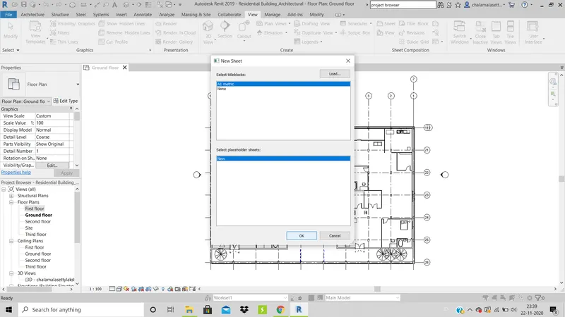
3. Click on view in view tab below sheets and option and open required view of building and paste it on sheets.
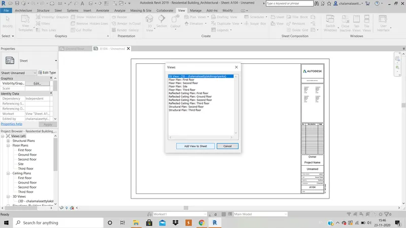
4. Change the name of sheet as required.
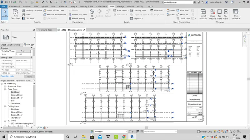
RESULT : I have created 3 sheets for elevation views, plan view, sectional view which ae shown below:
ELEVATION VIEW SHEET :
PLAN VIEW SHEET:
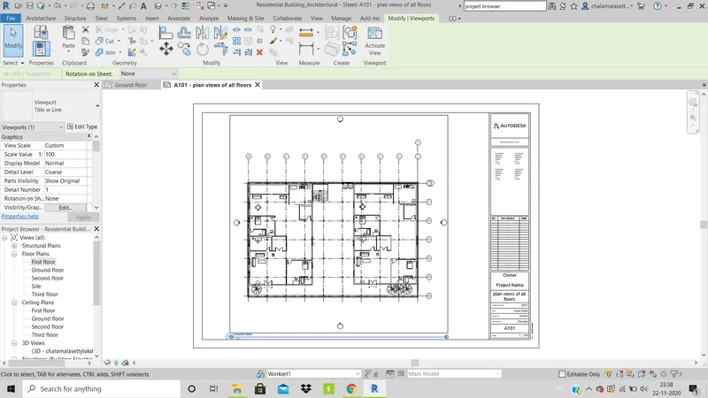
PS : As floor plans will be similar, i have only pasted ground floor plan in the sheet.
SECTIONAL VIEW SHEET :
6) Using the Rendering settings, Render images of 3D model produced and include the rendered images to the drawing sheets
a. Rendering from interior rooms
b. Rendering from out showing topographic features
c. Rendering through structural framing
AIM : To render 3D images of model and include rendered images to drawing sheets
TOOLS USED : View tab, Render, Region, Style, Scheme, Sheet
PROCEDURE :
1. Create 3D images of certain important places using camera view in View tab.
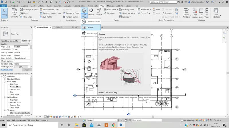
2. In the view tab, click on render tool.
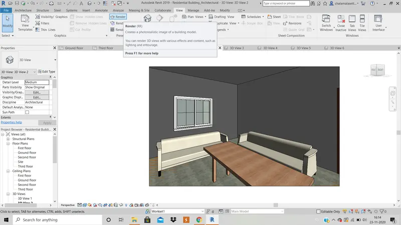
3. In the dialogue box that appears, tick on region option and properly slect the rgion and click on both sun and artificial lightning and click on render option.And click on save to project if the image rendered is proper.
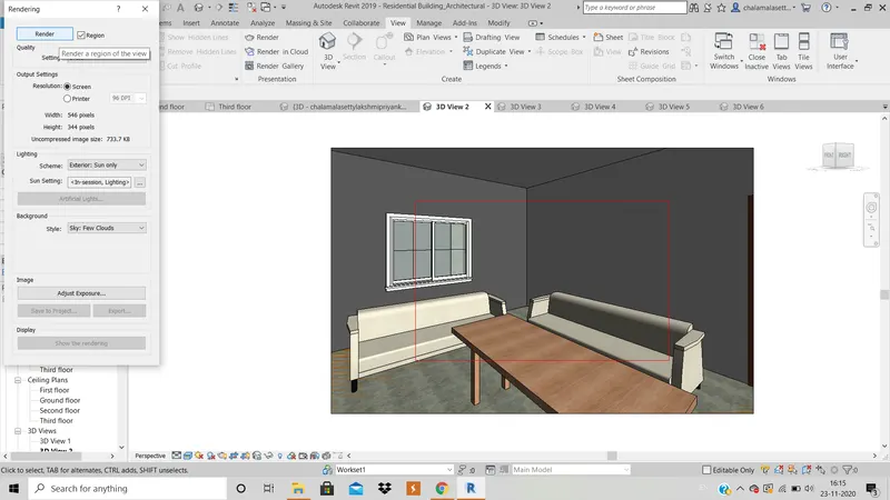
5. Now go to sheets in view tab and create sheets for pasting rendered images.
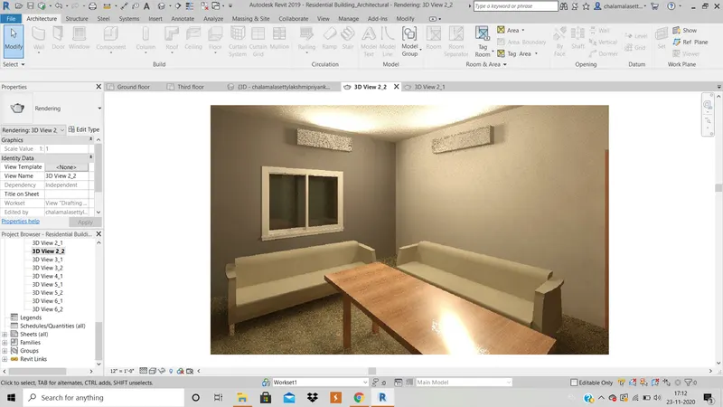
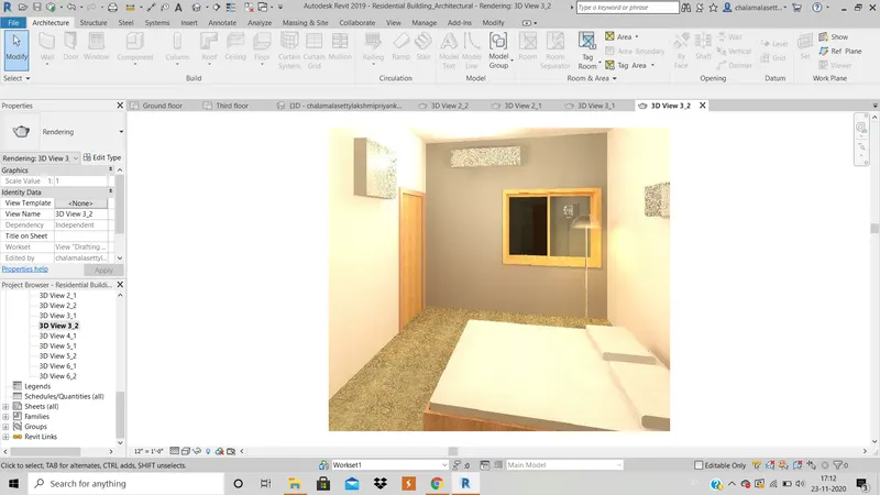
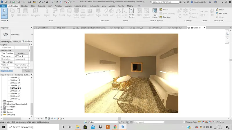
RESULT : The rendered images and sheets are shown below :
RENDERED IMAGES :
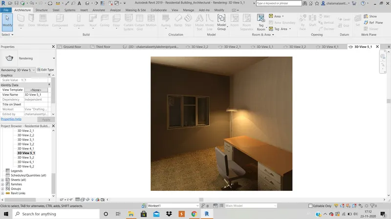
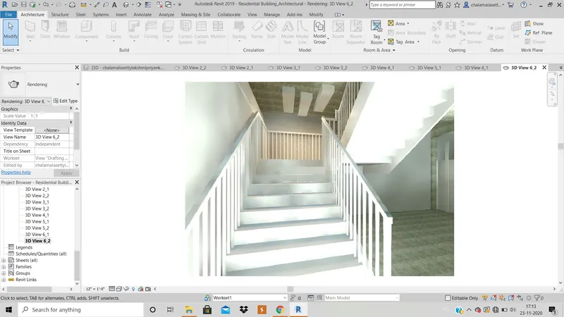
SHEETS WITH RENDERED IMAGES :
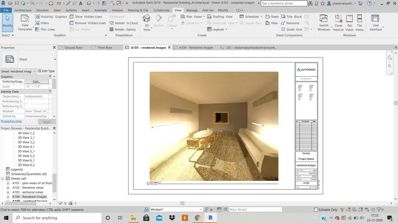
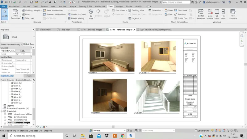
7) Print the set of drawing sheets created and submit the drawings from architecture and structure model
AIM : To print the sheets created.
TOOLS USED : Print.
PROCEDURE :
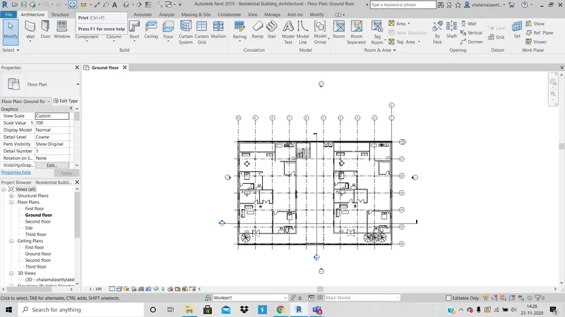
1. Open architectural or structural file and click on print tool which is present in the Quick access tool bar.
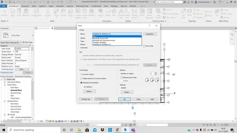
2. In the dialogue box that appears, choose required type of print options.
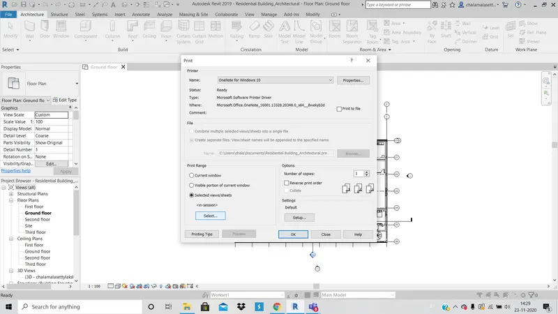
3. Click on slected views and click on select views.
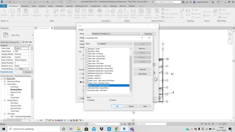
4. In the dialogue box that appears newly, click on sheets views and click ok.
RESULT : Due to pandemic situation, I am not able to submit the printouts.