REVIT_ Plan, 3D View & Structural Drawings_Project 2
1) Select the type of structure you want to build from one of the three below
a. Multi Unit Residential Apartment
b. Office Buildings
c. School
ans) I will select the multi unit residential apartment.
2)Assume reasonable assumptions for geographic and location details for your project modeling. Based on assumptions and type of structure selected identify the modeling requirements from NBC
- the details regarding geographic and location insisting my assumptions are:
- it is a resindetial unit.
- generally these kind of projects are located in plains.
- I am assuming the road width to be 30'.
- some of the NBC requirements for the project are:
- proper size of rooms according to NBC.(min 12sqm).
- proper drainage system
- good lighting and ventilation
- height of the building in considering with the width of the road.
3)Using the structural model, include the following components based on the type of structure selected
a. Foundation – Isolated / Wall/Matt Foundation
b. Columns
c. Beams Connected to Columns
d. Roof Framing/ Truss
e. Floor / Decks
f. Floor Openings for Elevators and Stairs
Aim: to create a structural model which should contain foundation,coloumns,beams, roofs, floors.
Tools used: several tools from structural and architectural tabs.
procedure:
- open the existing revit file which is already saved along with the grids 1 horizontal and 1 vertical.
- arrange the grids with equal distances say 32'.
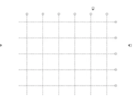
- Now arrange the levels namely foundation(-5'0"),ground floor(0'0"),first floor(12'0"),second floor(24'0"),third floor(36'0"),roof(45'0")
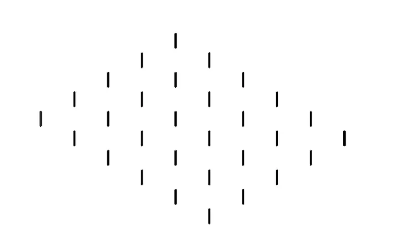
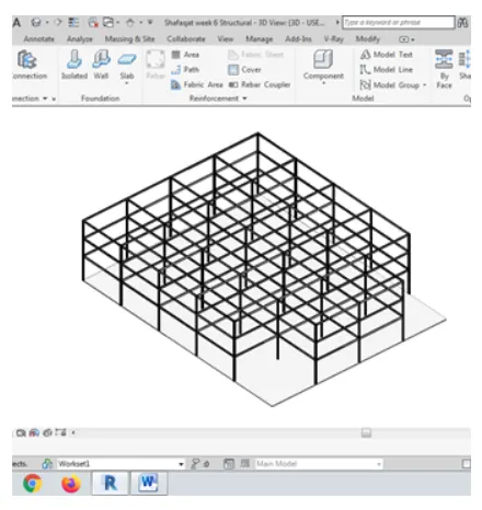
- from the structural tab select the coloumn property and select at grids property to acquire the coloumns at the intersection of the grids.
- and open the 3d view where you can see the arrangement of coloumns.
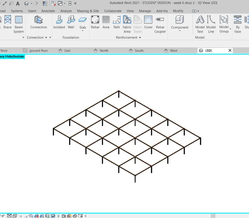
- go to the structural tab and select the beam property .
- choose pick lines and select the boundaries to placethe beam.
- now for creating foundations we have some three kind of ways but instead iam using slab foundation.
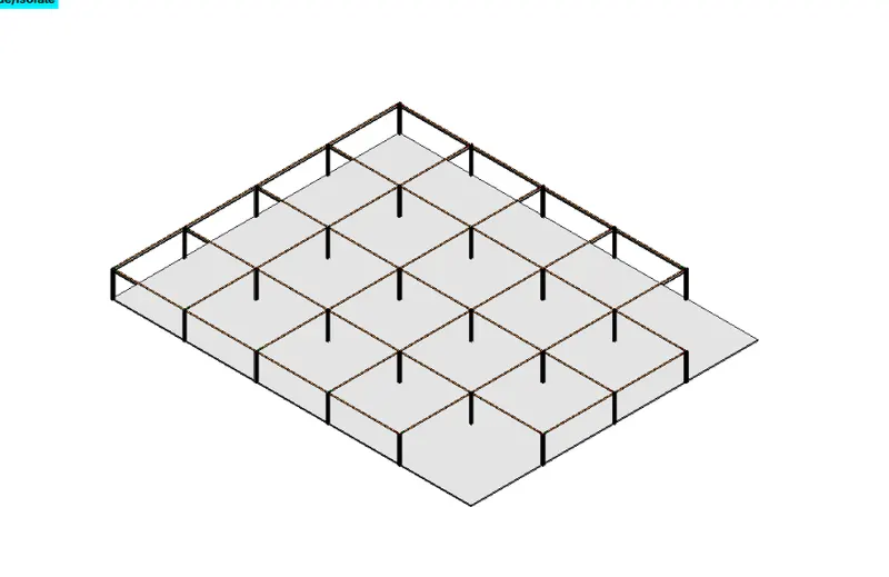
- select the entire model and use filter option and remove unwanted foundations.
- Now copy and paste it to all the floors.
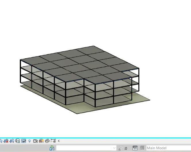
- select the floor property and set it to the ground floor and copy paste accorss all the floors.
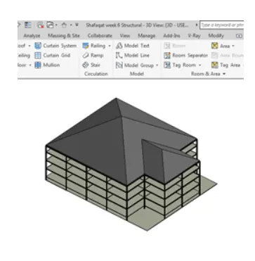
- now select the roof property and place the roof selecting the boundaries of the model and adjust the slope.
4) Using the architectural model, include the following components based on the type of structure selected
a. Wall Layout with appropriate material and finishing
b. Exterior façade with fancy finish
c. Interior partition walls to size rooms
d. Components to add details to room ( Desk, Chair, Lighting, Plumbing fixtures)
e. Add components such as stairs Elevators
f. Have at-least one side of building with curtain walls and glass panels
g. Include interior and exterior lighting fixtures
h. Place proper topographic components from outside ( Trees, Parking, Plants) to add details to the model
Aim: using the architectural model include several components based on type of structure selected.
procedure:
- open the same file and from that select the architectural file in that .
- you will see the model in the architectural file.
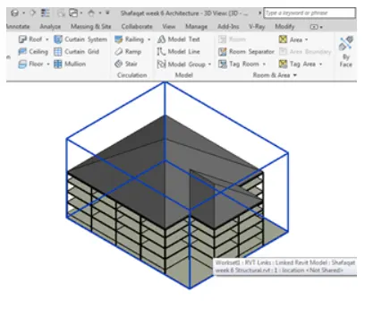
- now select the plan view from the view panle and then create plan view like ground floor,first floor etc.,.
- now from the architectural tab select the wall property and complete placing the walls.
- go to the properties window and adjust the base constraints.
- then the 3d will be seen as such
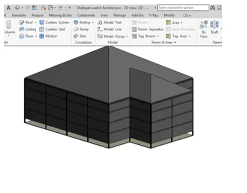
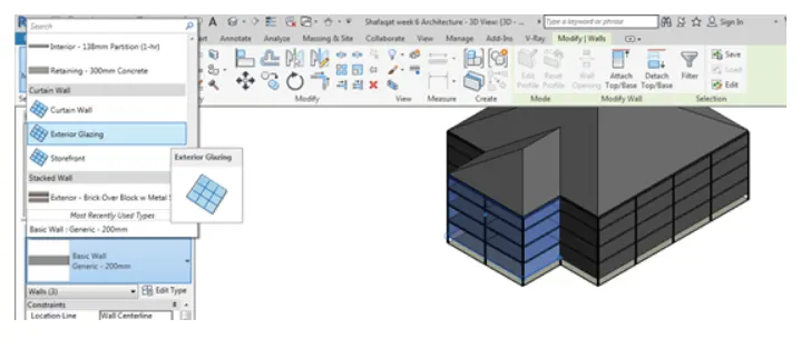
- select the walls at the front and make them as curtain walls.
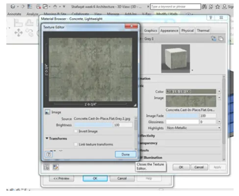
- from the properties panel select the wall material i chose it as lite concrete.
- open the ground floor view and select the interior walls and adjust the partition interior walls as required.
- copy these walls all together and paste these at every level using aligned to slected levls property.
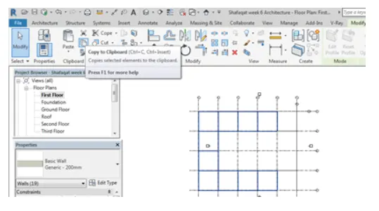
- select the floor architectural and place the floor all over the boundary with some extra extension.
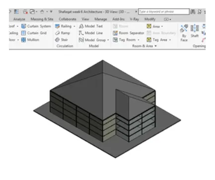
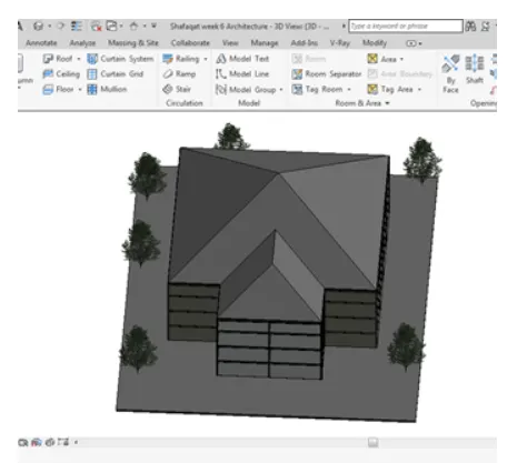
- from the properties click on families option and selec the planting option and place the plantings accordingly to the good aesthetic view.
- for the elevators go to the shaft opening option and select a proper opening for the building.
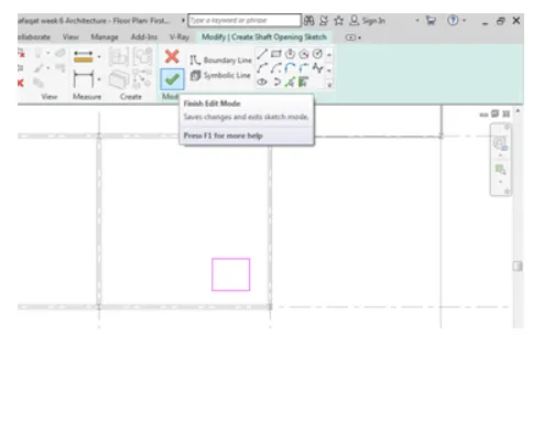
- after selecting the proper boundary for the elevators click on the finish button.
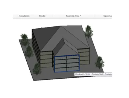
- select the opening created and from the properties window select the base constraint as ground floor and top constraint as third floor.
result:
5) Provide set of drawings in architectural and structural model to list the following details with categories and appropriate sheet templates included
a. Floor Plans with Annotations
b. Elevations
c. Sections
aim: to create sheet templates from the model which should contain floor plan with annotations,elevations and sections.
procedure:
- open the same architectural model file
- from the view tab select the sheet property where it is possible to create the new sheet.
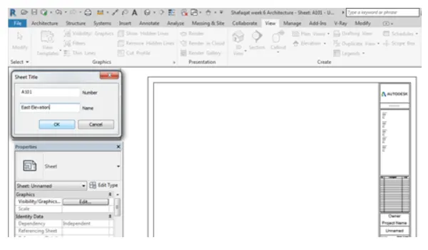
- so from the properties panel change the name of the sheet and neccessary other properties.
- firstly iam adding east elevation so i named the sheet as east elavation view
- from the view toolbar select the view property and it shows to which view to be added to the sheet.
- select east view and their you will see east elevation added on to the sheet.
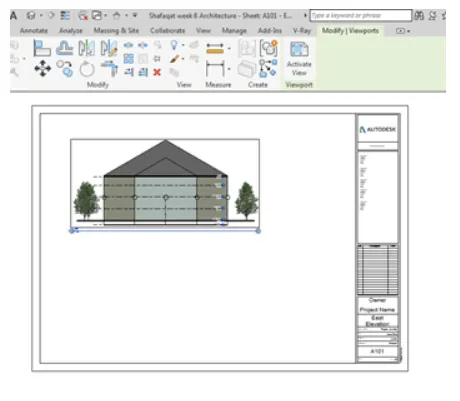
- in the similar way we can create many other elevations on to the sheets
- open another new sheets and this time we are going to add the sectional view on to the sheets
- then name the sheets as required.
- open the view property from the view tool bar and select the sectional view 1 and click on add view to sheet icon.
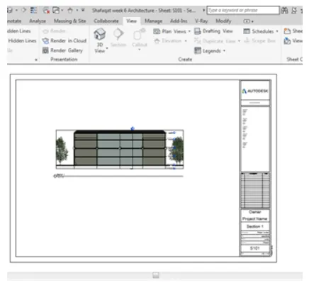
- we can clearly see the sectional view on the sheet.
results:
east elevation
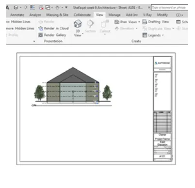
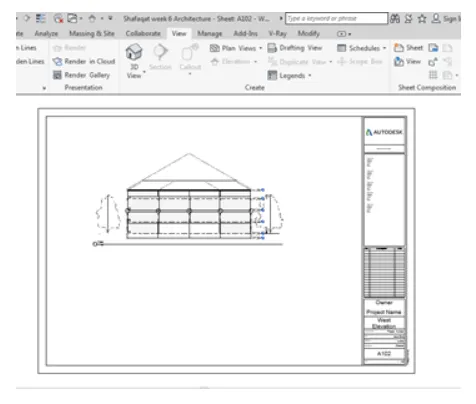
west elevation
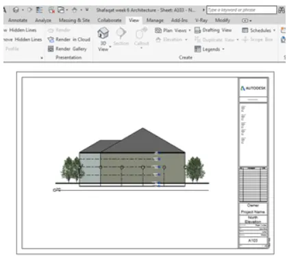
north elevation
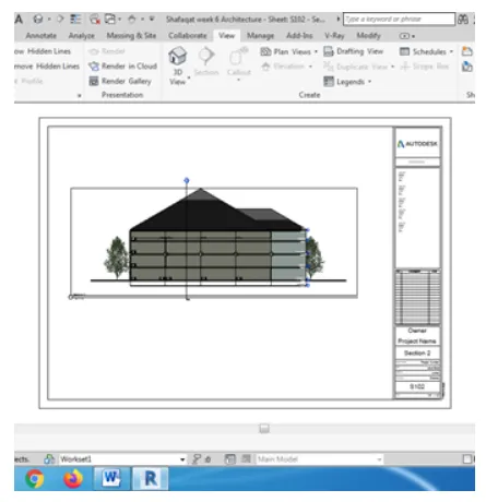
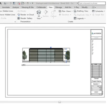
section views :
6) Using the Rendering settings, Render images of 3D model produced and include the rendered images to the drawing sheets
a. Rendering from interior rooms
b. Rendering from out showing topographic features
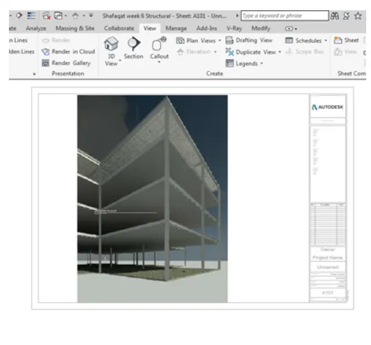
c. Rendering through structural framing
aim: to render the images of the 3d model and place them on the sheets
tools used:
- render
- view
- sheets
- properties
procedure:
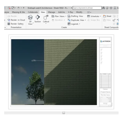
- select any 3d view for examle curtain glass view
- select the view tool bar and choose the render property
- a window will dropdown showing the neccesarry changes in the rendering settings usch as light settings.
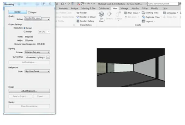
- now click on save to project option to save the rendered image
- and then a window will appear asking to name the rendered image
- name the rendered image accordingly
- you can see the rendered image form the project browser.
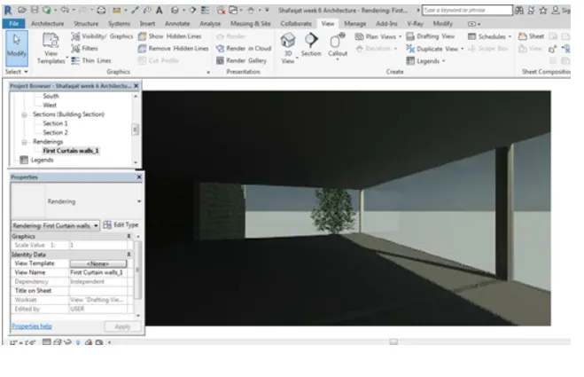
- in the same familiar fashion we can render other images also.
setting up the rendered images in the sheets:
- select the view bar and selec the sheet from that and create a new sheet.
- now from the same view bar seleect the view option and select the requied view that we need to add on the sheet.
- for now select the rendered images to add onto the sheet
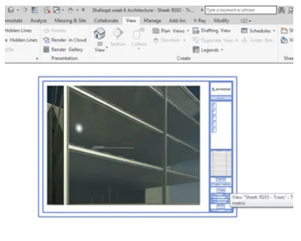
- in the similar fashion we can add the remaining rendered images.
result:
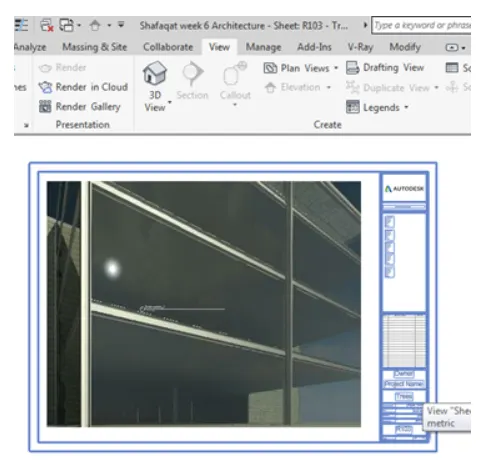
rendering of a structural model
7) Print the set of drawing sheets created and submit the drawings from architecture and structure model
aim: to print the set of drawing sheets from the model
procedure:
- from the left top corner of the revit working window you will find print option
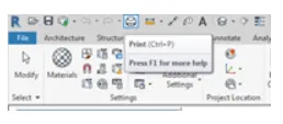
- after selecting that a window will appear what sheets should be choosed to be printed
- select the required set of sheets to be printed.
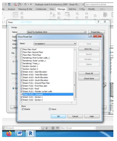
- setup a printer to print the sheets.
result:
set of required sheets are printed succ3essfully.