REVIT_Dynamo Project- 3
1) Using Dynamo create a set of sinusoidal points and create a curve and create a surface out of the curve.
AIM: To create a set of sinusoidal points and create a curve and create a surface out of the curve by using Dynamo.
TOOLSUSED:
- Manage
- Dynamo
- Code block
- math.sin
- Inteder slides
- Add
- pointsby coordinates
- surface by lost
PROCEDURE:
STEP-1:open the Revit software .create a new template
STEP-2:Save the file
STEP-3:Go to Manage tab and select dynamo tool.
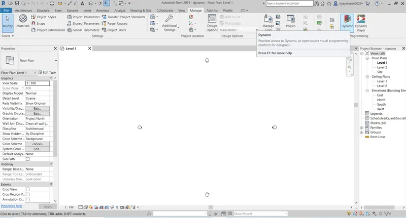
STEP-4:The Dynamo Workspace will open and click on New and now we start the work in Dynamo.
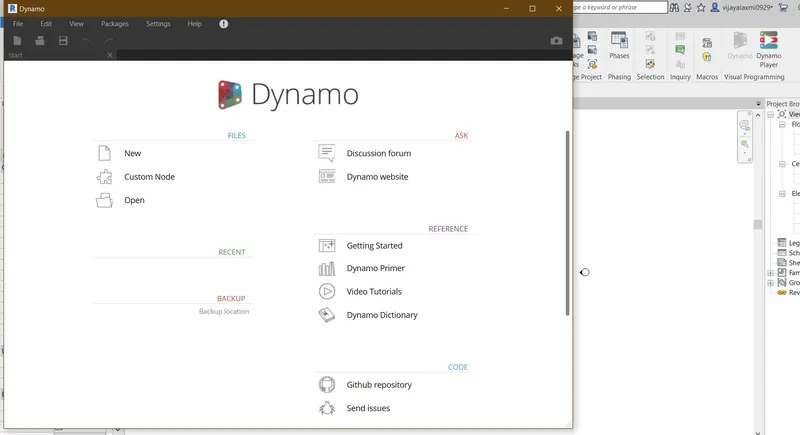
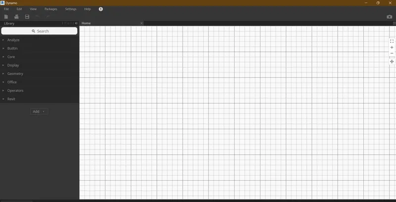
STEP-5:First to draw a sinusoidal ciurve we need certain parameters like start,end ,step we can get these by selecting the 3 code blocks from the library and rename them.
STEP-6:Now select the Range and By coordinates from the library.
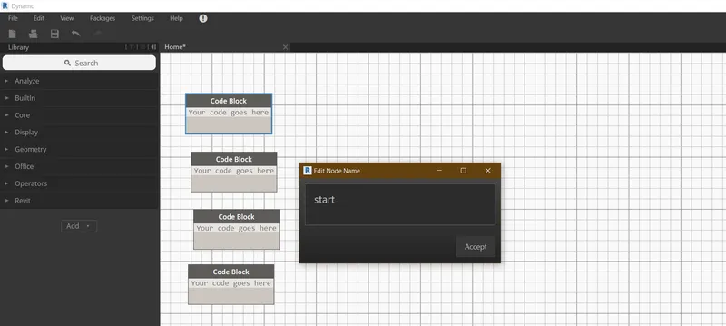
STEP-7: Connect the start end,step to the range and range to the point:by coordinates.
STEP-8:select the Math,sin parameter to draw the sine curve.connect the node to the range
STEP-9:select to add operaters and and name one of the operator as * .
STEP-10:Select one interger slider and connect it to the y of +.and also connect * to x of +.
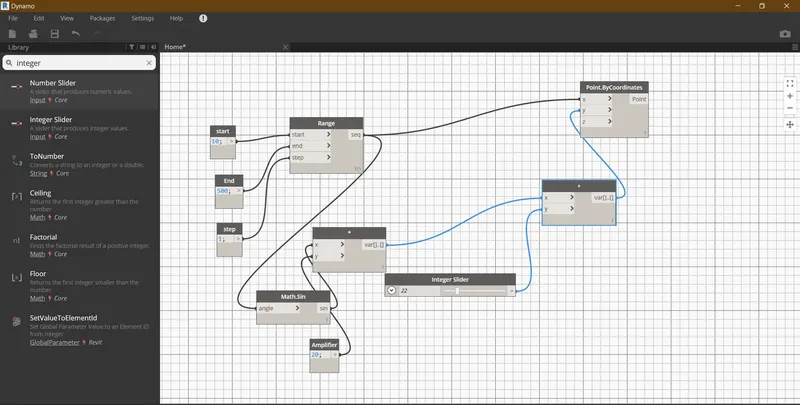
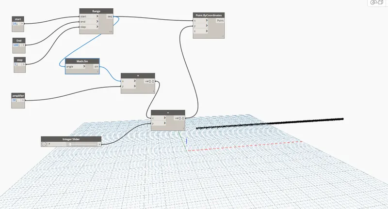
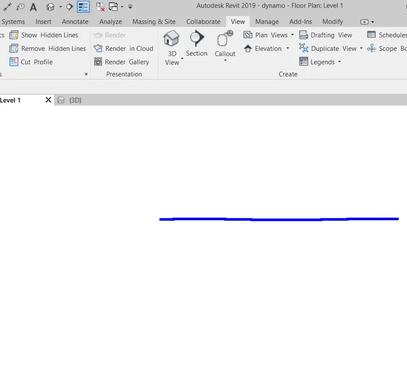
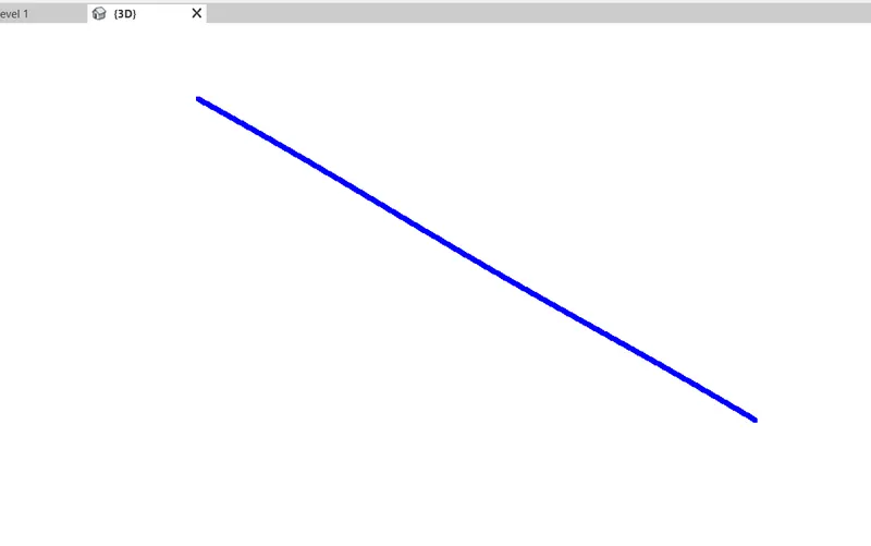
STEP-11: select the code and remane it as Amplifier and connect it to the y of *
STEP-12:select the integer slider and nama it as Phase and connect to the y of +.
STEP-13:select the NurbsCurve.Bycoordinates.join it to Pointby: coordinates.
STEP-14:Select all the nodes and go to the Edit and select Create node from selection.
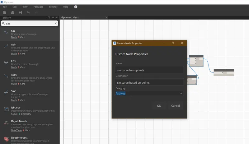
STEP-15:Sin curve with inputs will appear copy the sin curve and connect them.
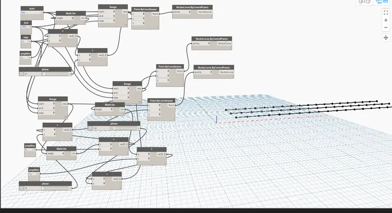
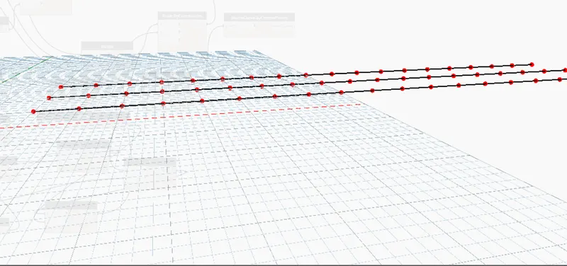
STEP-16:select the List create and connect the each item to each sincurve.slect the surface loft .
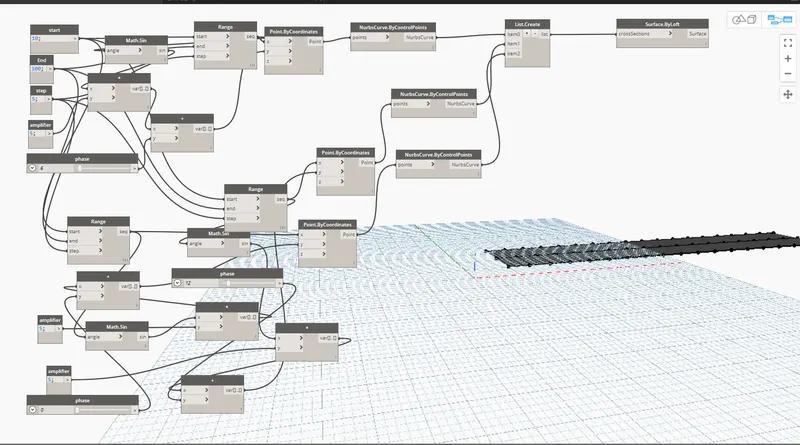
RESULT:
By following the above step we can create the sinusoidal points and curve and surface out of the curve successfully.
2) Create a conceptual layout of floor plan in dynamo . Using the tools available in dynamo link the lines to appropriate model elements in Revit by choosing the wall types and wall parameters. Make use of the sliders to slide through the height of the wall and length of the wall.
AIM:To create a conceptual layout of floor plan in dynamo , by using the appropriate model elements like wall types and wll parameters and use the sliders to slide through the height of the wall and length of the wall.
TOOLSUSED:
- Dynamo
- codeblock
- Point by coordinates
- Integer slider
- wall types
- levels
- wall by curve and height
PROCEDURE:
STEP-1:open the architectural template in revit
STEP-2:Go to Manage tab and open dynamo
STEP-3:The dynamo work space is created .Create a new window
STEP-4: Create four controlpoints by selecting By coordinates from library
STEP-5:Rename the coordinates as origin(0,0,0),Control point1(x,0,0),Controlpoint2(0,y,0),Controlpoint3(X,Y,0).
STEP-6:Now create two number slides and rename them as X,Y
STEp-7:The x parameter cannot be zero so assign aas 10 and step as 1
STEP-8:Then, connect the nodes of X to the Control point 1(x,0,0)and control point 3(x.y,0).
STEP-9:Then connet Y to the Control point 2(0,y,0) and control point 3(0,y,0).
STEP-10:Now go back to our modelling work space we can see all the points
STEP-11:Next function is Line:By start point end point ,select four lines .
STEP-12:The first line is between (0,0,0) and (x,0,0) ,The second line is going to be between (0,y,0)and (x,y,0)
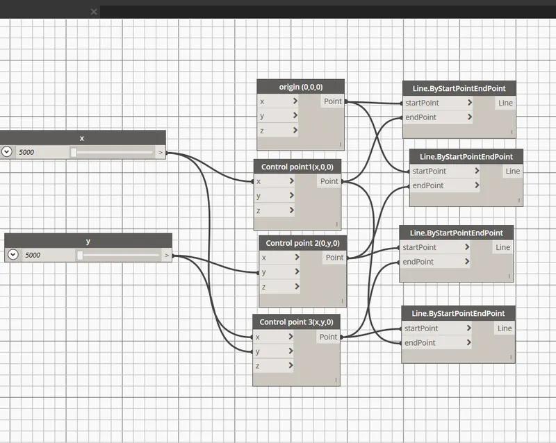
STEP-13:The node end point of first line is connected to thestart point of second line.
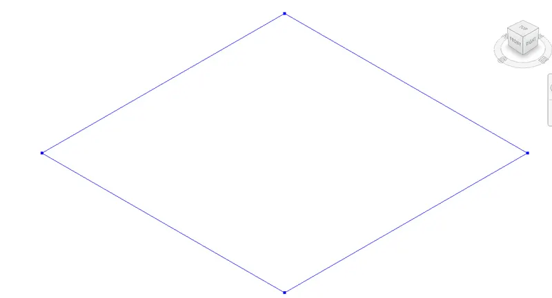
STEP-14:Select wall: by curve and height and assign input parameters by selecting wall types ,levels, number sliders and name as Height of wall.
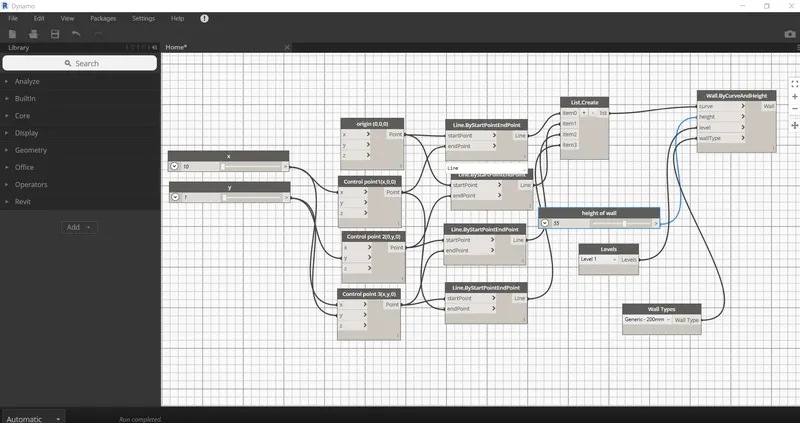
STEP-15: select the list create and join all the lines to it
STEP-16:Now assign all the parameters to wall: by curve and height.
STEP-17: Go to view window and view it in revit .
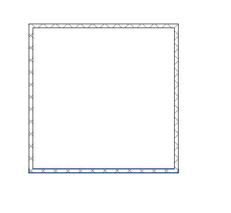
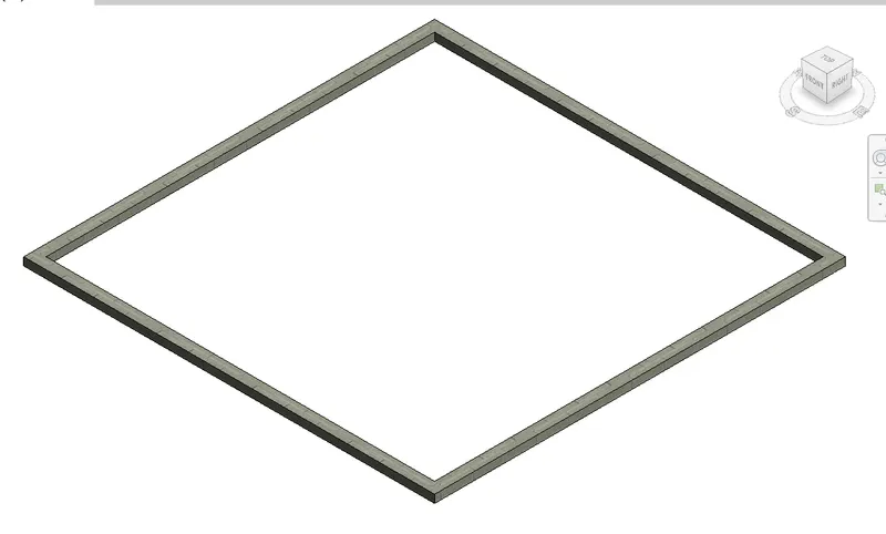
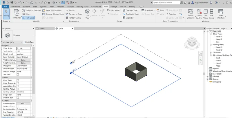
RESULT:
The conceptual layout for the floor plan by including the parameters like levels,height walltype,length is successfully created in the dynamo and viewed in 3D.
3) Create an array of model elements in Revit. Use dynamo to vary the properties of model elements by using the slider or code block
AIM:To create an array of the model elements in revit .
TOOLSUSED:
- Family
- Referance plane
- Generic model
- Extrusion
- void form
- Label
- Generic model wall based
- save
PROCEDURE:
STEP-1:Open the revit family.
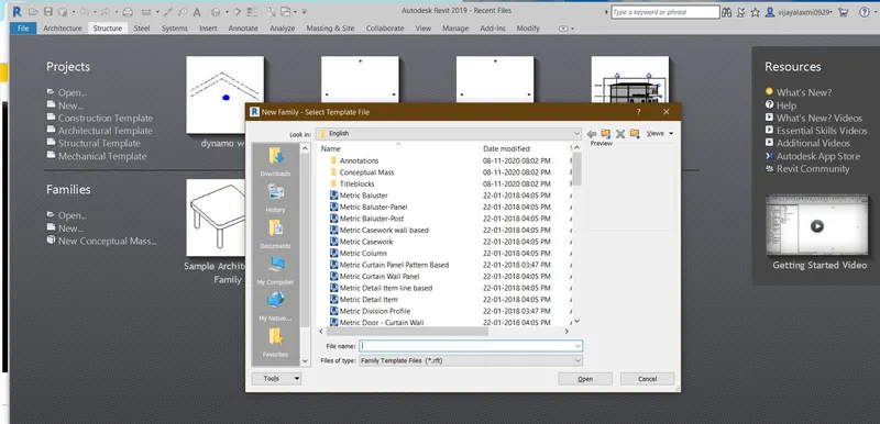
STEP-2: select the Generic model and click open
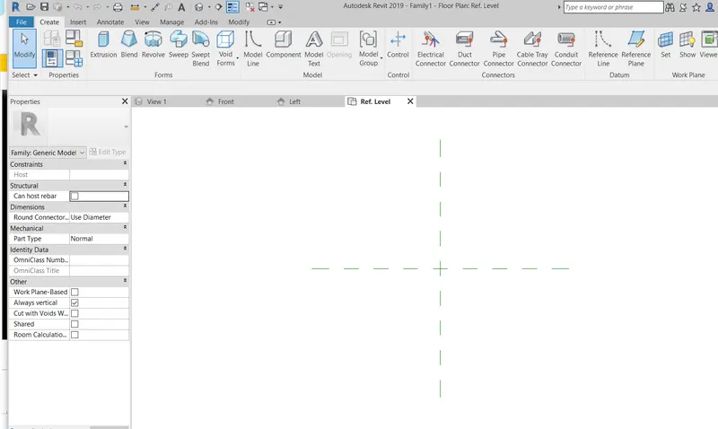
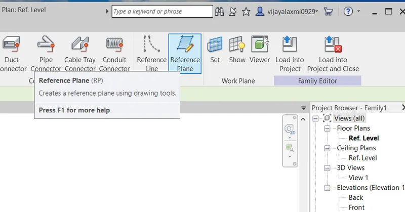
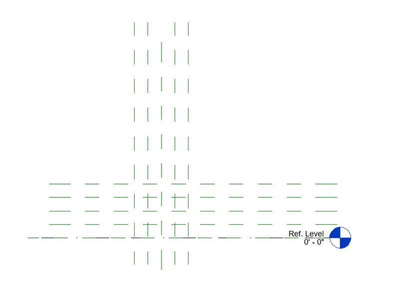
STEP-3:Select the create and click on referance plane and create reference planes at an offset.
STEP-4:Next , select the Extrusion and and click on curves and pick lines to draw the model.Click ok
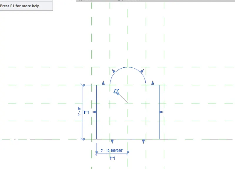
STEP-5:Align the reference planes to the phase of our model .
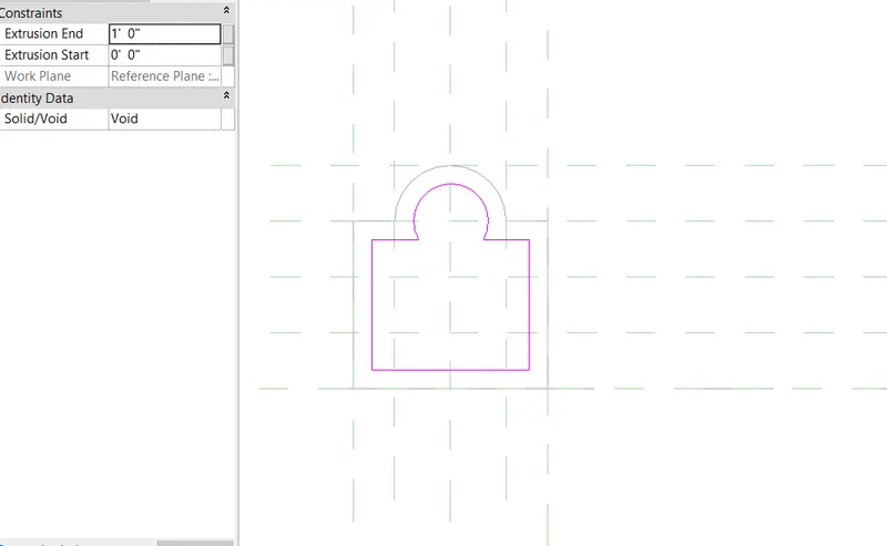
STEP -6:Click on void extrusion in create and enter the offset and place them.
STEP-7:Align the dimensions and save it .
STEP-8:Go to file and families and select the generic model load based.
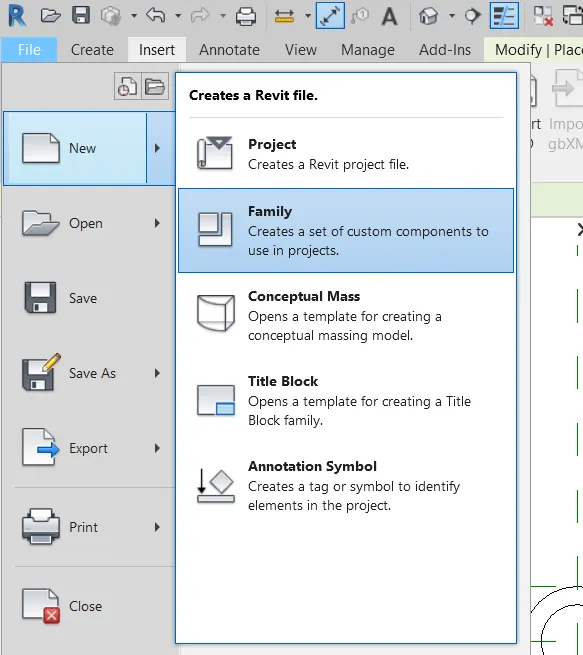
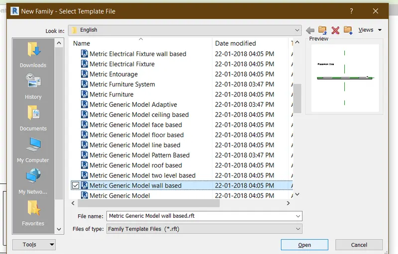
STEP-9:click on load to project and it is loaded in to the template.
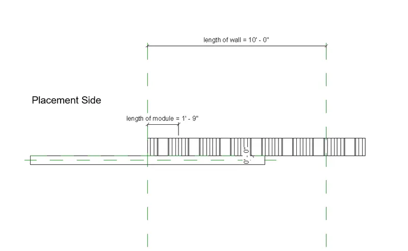
STEP-10:Create arrays of the model.and draw a offset.
STEP-11: Go to annotate and align the module length and wall length .
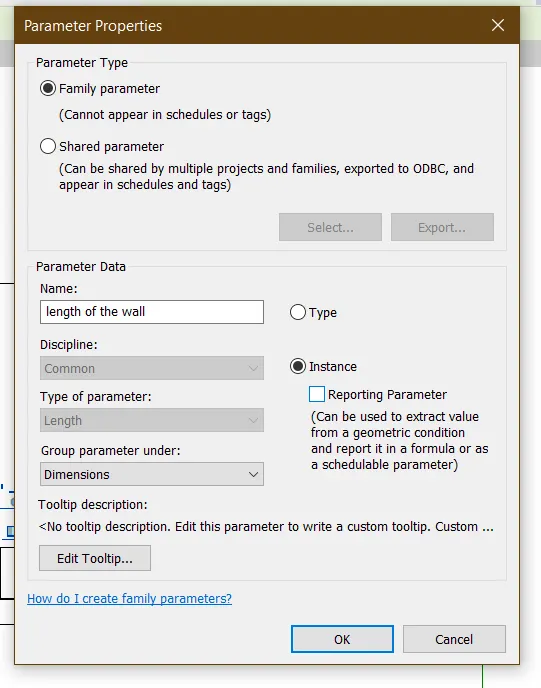
STEP-12: Add the labels and Rename them .
STEP-13;Go to properties and write the formula for quantity and click on apply.
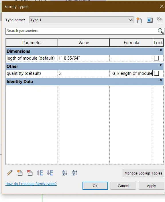
STEP-14: Save them with the name and take the Architetural template and load the family in to it
STEP-15: View them in 3D we can view the design module on wall.we can align the elevation,length in properties browser.
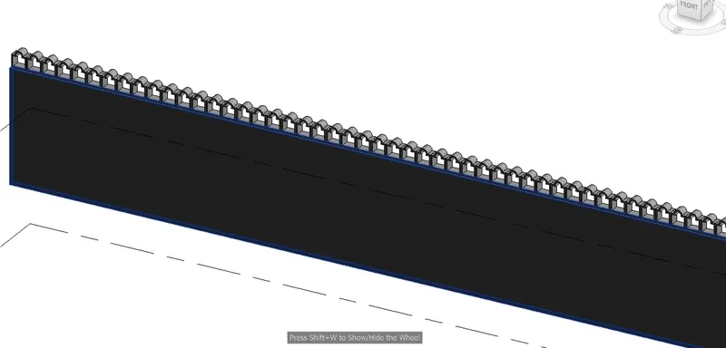
RESULT:
The array of elements are created and saved in the familes in the revit and viewd in 3D sucessfully .
AIM: By usimg the dynamo to vary the properties of model elements by using the slider or code block
TOOLSUSED:
- Architectural template
- Columns
- Dynamo
- Integer block
- select model elements
- code block
- view
- set rotation
PROCEDURE:
Step-1:Firstly,open the Architctural template in the revit software
STEP-2:Next select the columns in the Architecture tab and draw the columns
STEP-3:Then go to manage tab and select the dynamo.
STEP-4:Go to new now the new work plane is created .
STEP-5:go to lybraries and search the select model elements. and now click on select and go to revit and select the columns.
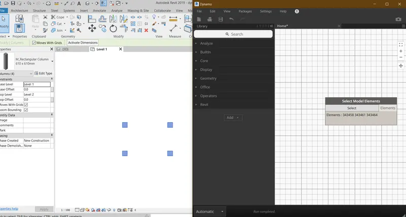
STEP-6:Add the set rotation,codeblock and number slider parameters.
STEP-7:Give the standard value to the code block and connect the codeblock and select model elements .
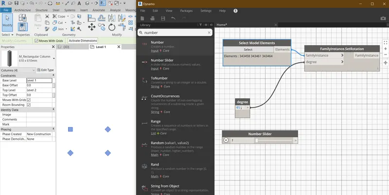
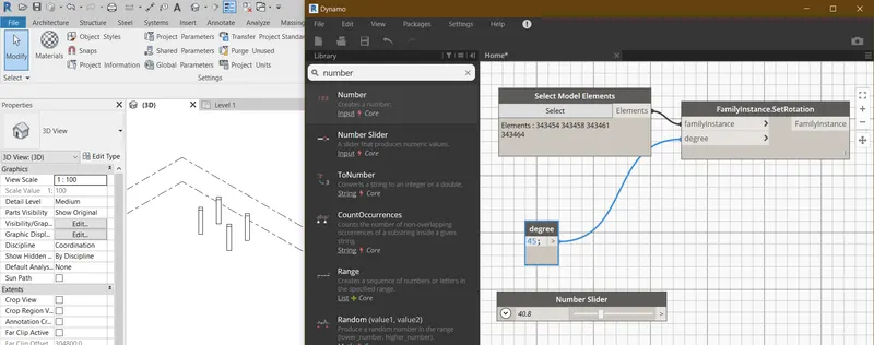
STEP-8: now connect the interger slider to set rotation of column
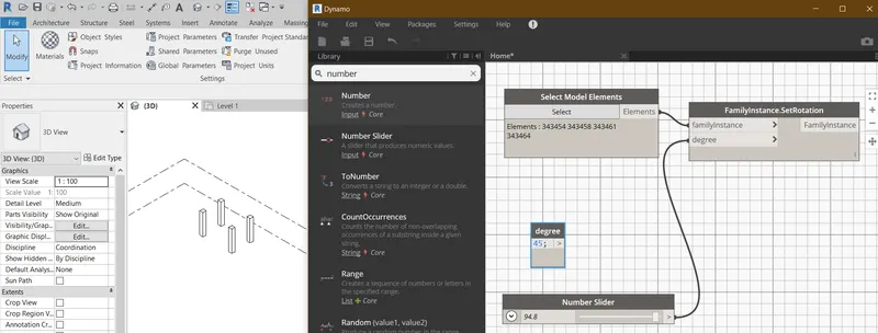
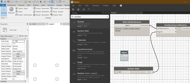
STEP-9:Now by changing the integer values we can see the changes in the revit simultaneously.
RESULT:
Now the properties of model elements in the revit are changed successfully by using the code block and number slider in the Dynamo.
4) Create a conceptual mass in Revit and develop a parametric column by dividing the surfaces and apply the concepts similar to used in parametric walkway modelling. Use triangular bent or square shaped panels to add finish to the parametric column
AIM:
To create a coceptual mass in the revit and develop a parametric column by dividing the surfaces and apply the concepts similar to used in parametric walkway modelling adnd using the traiangular bent or square panels to add finish to the parametric column.
TOOLSUSED:
- Families
- new
- coceptual mass
- level
- line
- reference points
- Divide surface
- create form
- Filter
PROCEDURE:
STEP-1:Open the Revit .click on New in the families a dialouge box appears select the Coceptusl mass .click open
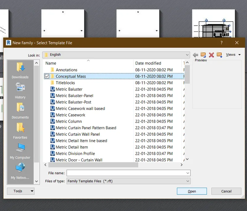
STEP-2:next the conceptual mass work space opens
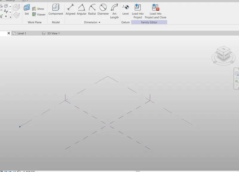
STEP-3:Now go to any of the elevation view and Draw the Level at an offset of 10'
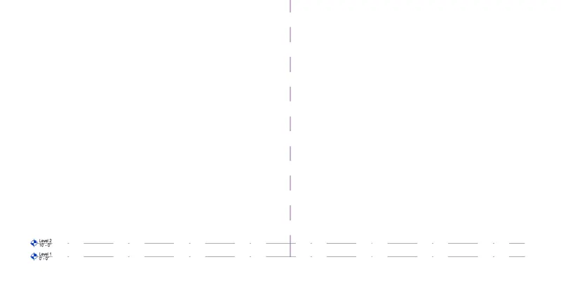
STEP-4:Now select the LIne and draw the line. and put the reference points on the line at appropriate distances.
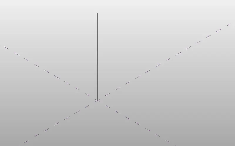
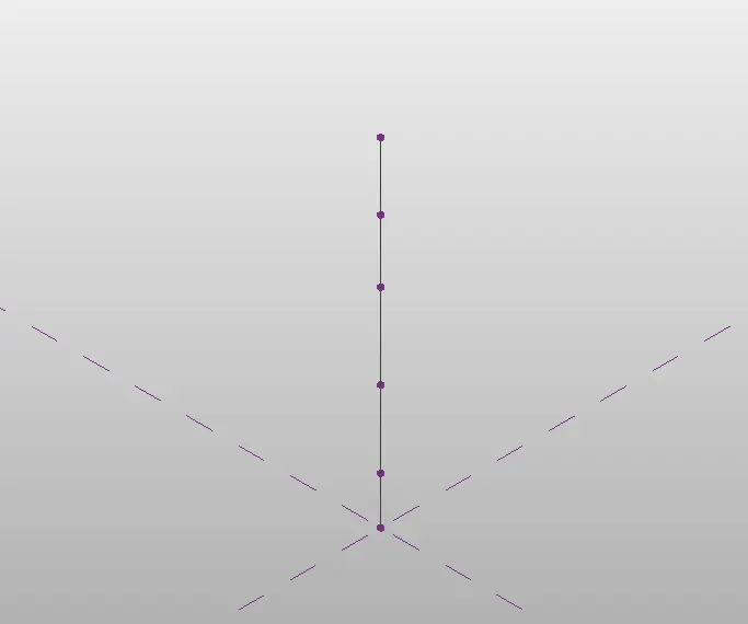
STEP-5:Now Go the 3dview and set the planes and inscribe the polygon in them .
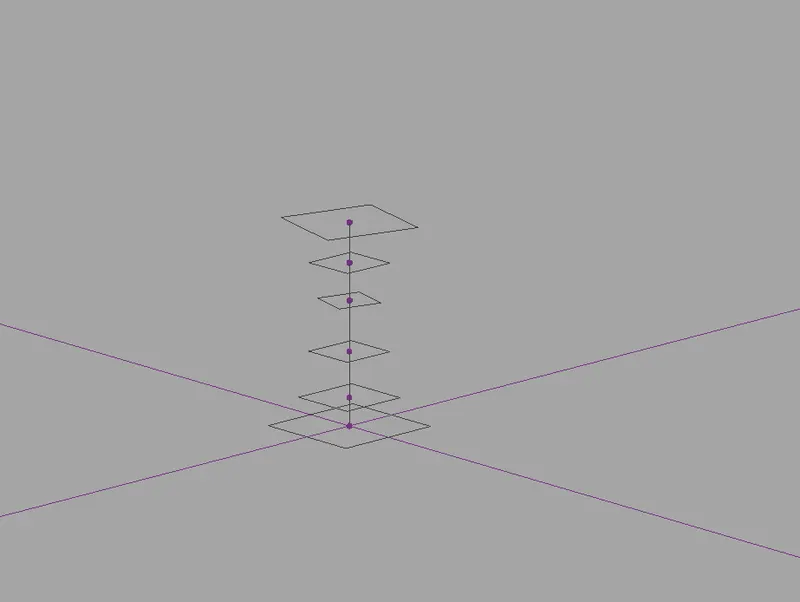
STEP-6:Select the components and click on the create form .
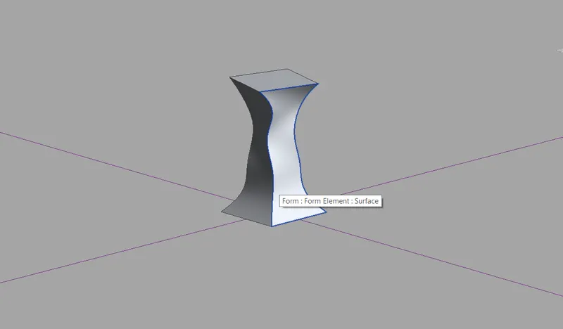
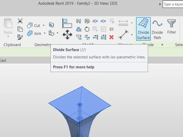
STEP-7:Select the elements and click on DIvide surface tool.
STEP-8:Now go to File >New> families and select the curtain panel pattern based and click ok
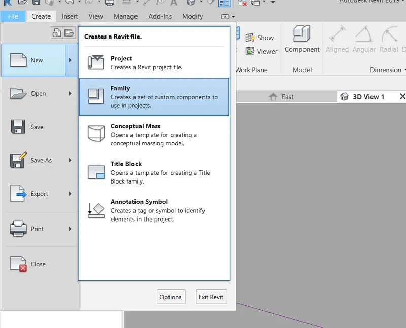
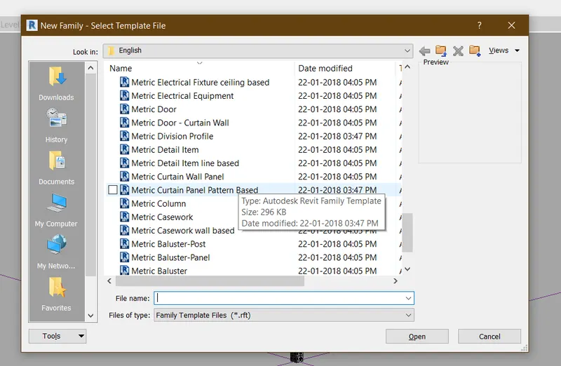
STEP-9: Here we can create our own patterns and save them and load them into the project
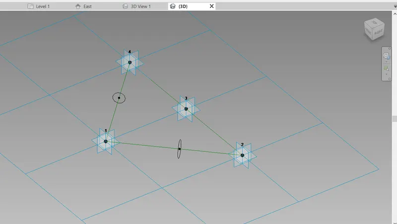
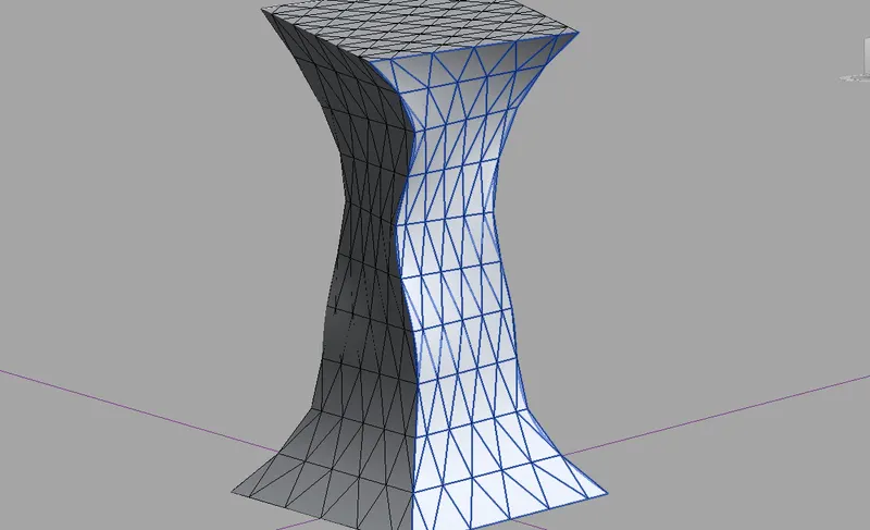
STEP-10: To my column i have selected traiangualr bent.
RESULT:
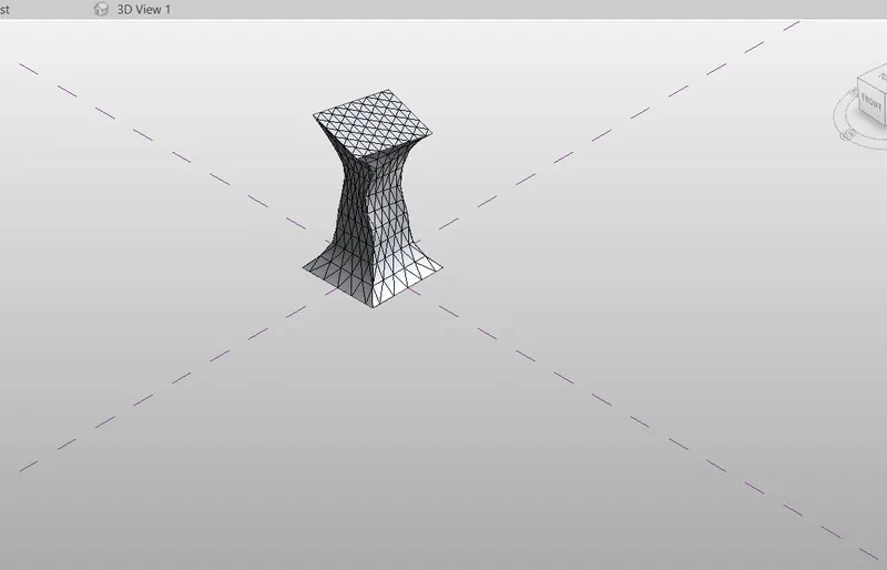
The conceptual mass is created in Revit and a parametric column is developed by dividing the surfaces and using the traiangular bents as a finish to the columns sucessfully. with the above steps we can able to draw any of the parametric feature in the revit.
5) Use Dynamo to work on developing a Parametric Stadium. List your parameters and use the visual programming approach to complete the modelling, You can use the concepts discussed in parametric high rise tower in class for reference.
AIM:To create a parametric stadium with the help of Dynamoand to list the parameters by using the visula programing approach to complete the modelling.
TOOLSUSED:
- Dynamo
- Integer slider
- Code block
- Coordinate system by origin
- Rectangle by width and length
PROCEDURE:
STEP-1: open the Revit and create a Architectural template.
STEP-2:Go to Mangetool and click on Dynamo.
STEP-3:Create a new work place ,and Go to library and select the 4 Integer sliders .and assign them as Number of levels,Floor to floor,Bottom floor rotation,Top floor rotation.
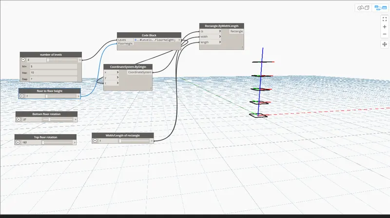
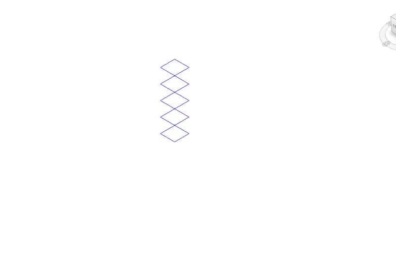
STEP-4:Create a code block and add the parameters like levels and flooor height and connect them .
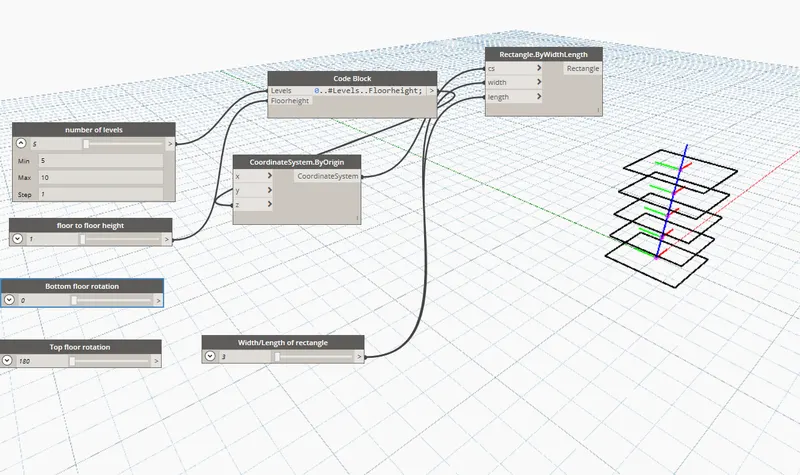
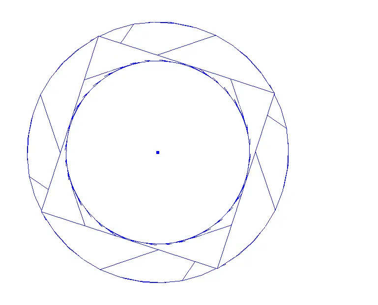
STEP-5: Add the Coordinates by origin ,Rectangular:By width length and Integer slider rename it ad width/length of rectangle.
STEP-6: connect the width/length of rectangle to width and length in the Recatangle :by width length.and connect coordinates of origin to the codeblock.
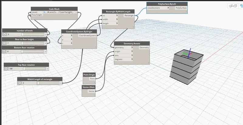
STEP-7:Connect the node of coordinates suystem by origin to cs of rectangle by widthlength.
STEP-8:Create a point origin and Vector,zaxisand Geometry rotate and a code block .
STEP-9:connectthe nodes of point origin and vector z axis to the origin and axis in the geometry rotate parameter.
STEP-10:Create a code block for bottom,topand levels and connect thenm.and connect the node of codeblock to degree of geometry rotate .
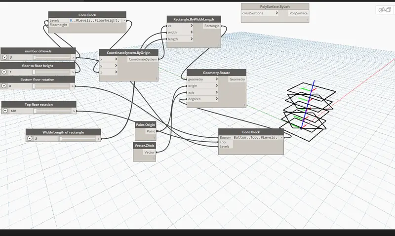
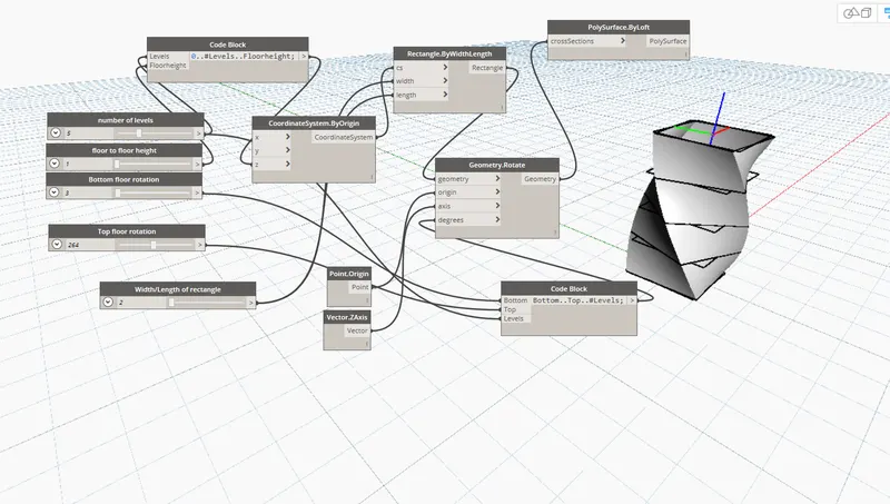
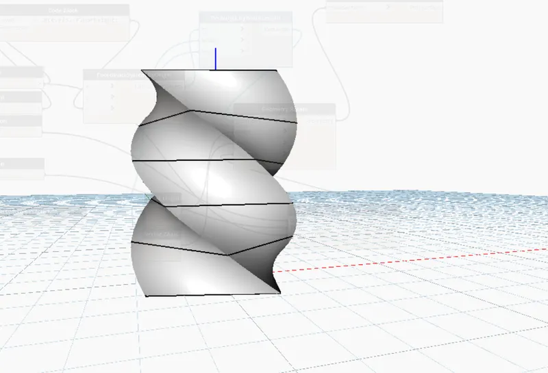
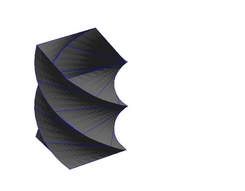
STEP-11:create a poly surfaec by loft and connect the nodes of geometry rotate to it .
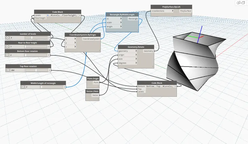
STEP-12: now change the parameters like number of levels ,floor height and view the changes in the model.
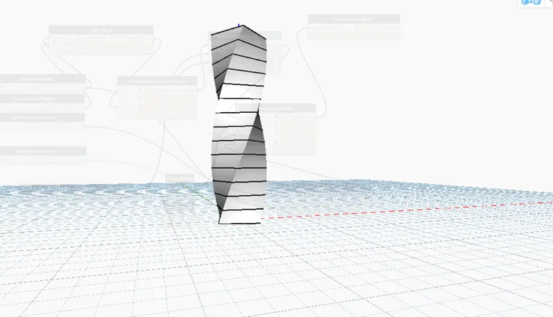
STEP-13: We can also change the width and length of the model and angle of rotation for both top and bottom
RESULT:
By using the above steps we can able to create a Parametric stadium of desired height,width ,shape in dynamo and we can can see the view in revit as wel successfully.