REVIT_3D Rendering of a House plan_Project 1
1) Based on the project saved from Week 3, proceed from First Floor Level .Model a Ceiling from architecture tab above the walls at first floor level
AIM:To Model a Ceiling From the architecture tab above the walls at first floor level.
TOOLSUSED:
Open
Architectural tab
Ceiling
Projectbrowser
PROCEDURE:
STEP-1:Firstly, open the revit software .
STEP-2:Then,Go to open and select the project which is saved in week-3.Click open.
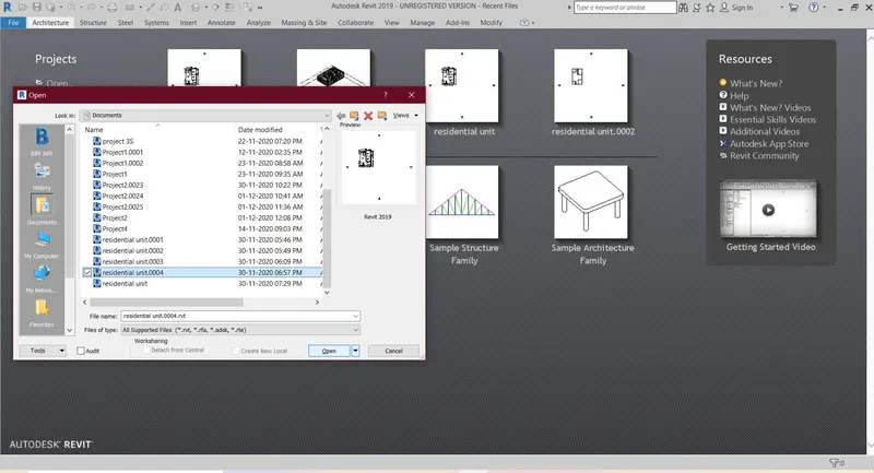
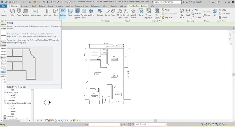
STEP-3:Now ,the model is viewed in the model space.
STEP-4:You will find the Architectural tab,In that select the ceiling .
STEP-6:Select the sketch ceiling .and click picklines and select the boundaries of the model and click the green right mark.
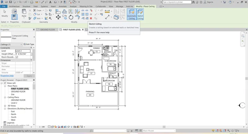
STEP-5:Before that rename the floor plan views i.e level-1 ,level-2 as Ground floor and First floor by double clicking on them in properties browser.
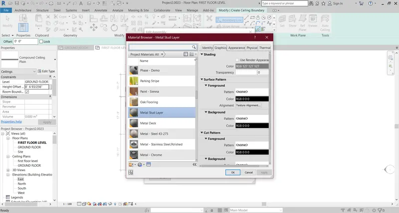
STEP-6:Now,Go to the properties browser and select the edittype and select the type of ceiling you need.and change the tickness.CLICK OK.
STEP-7:Now view the model in the 3D view.
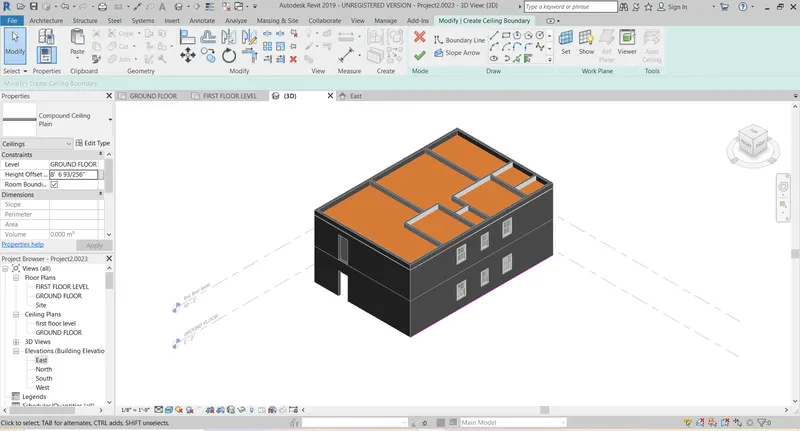
RESULT:
The Ceiling to the walls above first floor level is created Successfully with the required material and thickness.and viewed it in 3D.
2) Model a roof above the ceiling by selecting the footprints of ceiling. Using the adjustment tool bars appearing on screen adjust the roof slope to 10 degrees.
AIM:To Model a roof above the ceiling with a slope of 10 degrees by selecting the footprints of ceiling .
TOOLSUSED:
Architectural tab
Roof
Roof by footprint
Properties
PROCEDURE:
STEP-1:Open the previous model which we have created.
Step-2:Create another level as roof .By adding the level in elevation.
STEP-3-:Select the Architectral tab and then select the Roof which is present in the ribbon.and then roof by footprint
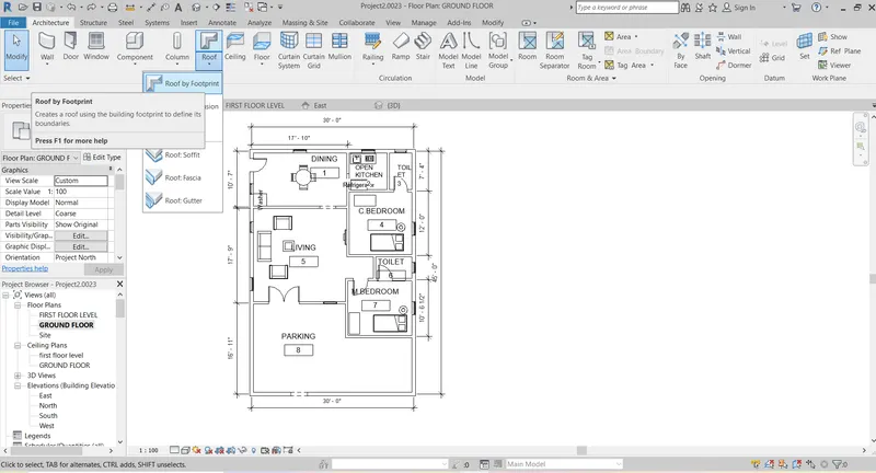
STEP-4:select the level in which you need to insert the floor ex,Roof
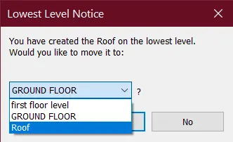
STEP-5:Select the boundary of the model .and click right mark in the mode.
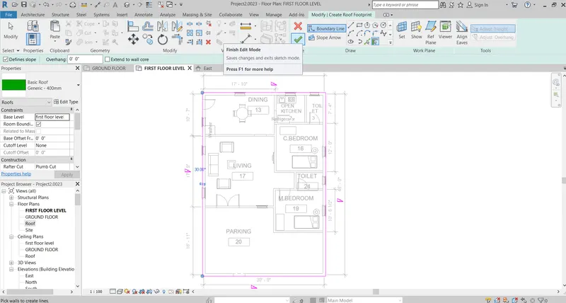
STEP-6:Go to the 3D view to view the roof.
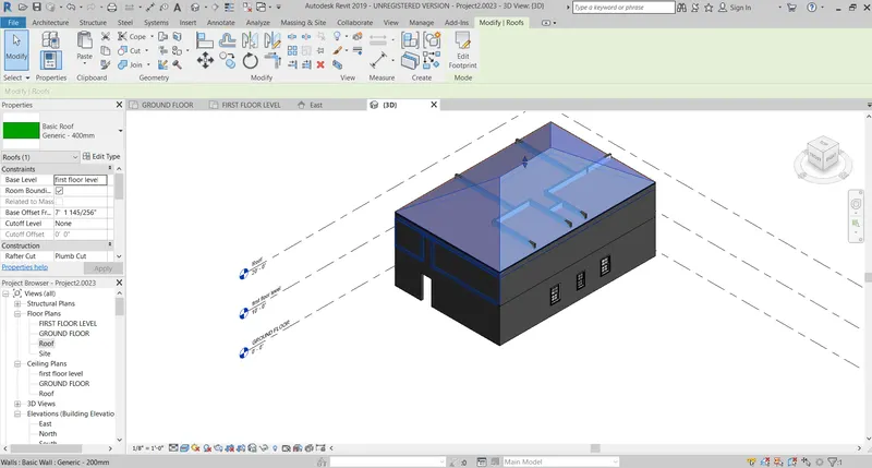
STEP-7:Now,Go to the properties and in Dimesions change the angle of slope to 10 degrees and Cick apply
STEP-9:Go to the propreties browser and select the material that is required for the roof.
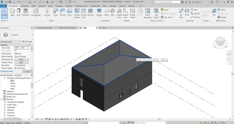
RESULT:
The roof is successfully created to the model with the appropriate material and having the slope of 10 degrees .
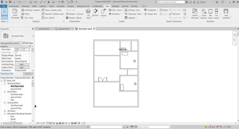
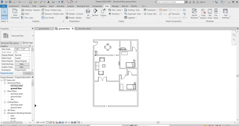
3) Using the file saved from week 2 to 4, create plan views for ground floor level and first floor level including all the walls , floors and components. Separate them to
architecture and structural plans
a. Architecture plan must have walls , floors and all the components placed within the building
b. Structure plan must have details of only walls, floors and columns
AIM:
To Create Plan views for Ground floor level and first floor level and seperate them to Architectural and Structural plans.
TOOLSUSED:
STRUCTURAL PLAN
VIEW
OPEN
PROCEDURE:
Step-1:Open the Revit software.
STEP-2:select open and select the previous saved file in week-2.
NOTE: The models that we prepared from the weel-2 to 4 are already the architectural plans it includes walls ,floors and components. Edit the name to the levels and
copy and paste the ground floor to the first floor level.Rename the Floor plan as Architectural plan.
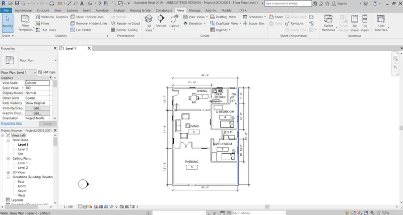
STEP-3:select the view tab and go to plan views and select Structural plan in that and and select the both levels.
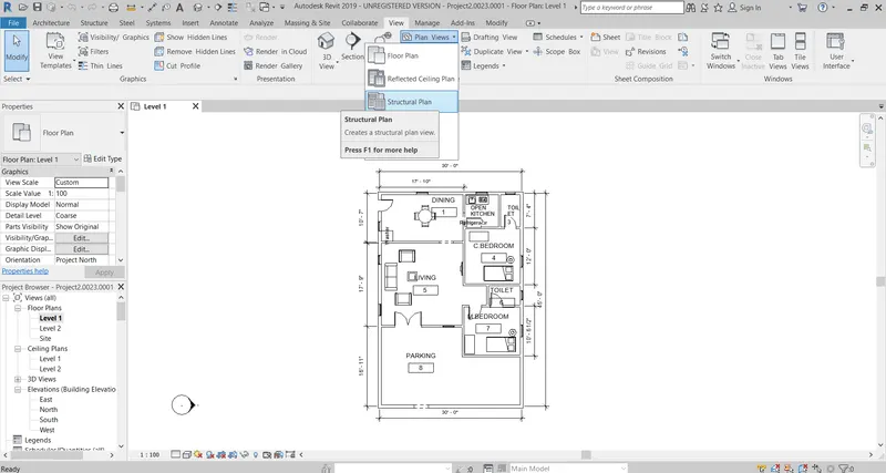
STEP-4:Now you can able see the structural plan for both first floor and ground floor.
RESULT:
The plan views of ground floor and first floor are created in Architectural and structural plan Successfully.
4) Using annotate tool bar add dimensions to all the walls and floors with reference to the longitudinal and transverse grids created in the project file
a. The architecture plan dimensions include details on where the components are placed within the buildings with relation to grids. Overall dimensions are sufficient for architecture plans
b. The Structure plan dimensions must include details on position of all the walls and interior walls with reference to grids. Locate all the framing components of the building with reference to a fixed point using Structural plans
AIM:To Add Dimensions to all the walls and floors with reference to the longtudinal and traverse grids by using the annotatetoolbar.
TOOLSUSED:
Architectural tab
Grids
Annotatons
Dimesions
Aligned
PROCEDURE:
STEP-1:Open the Revit file.It is a Architectural plan.
STEP-2:Select the architectural tab and then select the grids
STEP-3:Draw both the Horizontal and vertical grids and name the horizontal as A,B,C,D from top to bottom and vertical as 1,2,3 from right to left.
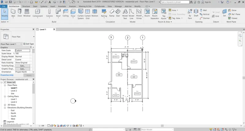
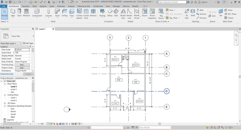
STEP-4;select the Annotate toolbar and go to Aligned and find the dimensions between the grids
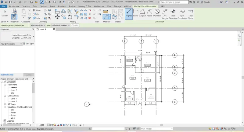
STEP-5:do the same procedure to the structural plan to align the dimensions between grids.
RESULT:
The Dimensions between the grids are Aligned for both Structural and Architectural plan by using Annotate tool bar successfully.
5) Create a sheet template from the view tab and adjust the parameters on the sheet to add appropriate views
AIM:To Create the Sheet template from the View tab and Adjusting Parameters on the sheet to add appropriate views.
TOOLSUSED:
Sheet
load
View
PROCEDURE:
STEP-1:Select the View toobar and then Sheets.
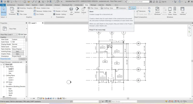
STEP-2:A new sheet dialouge box appears in that we can see load click on that you will find Title block familie with various sizes of sheet select the size of sheet required.click ok.
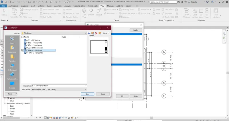
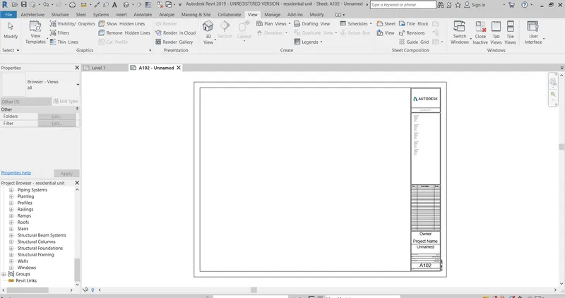
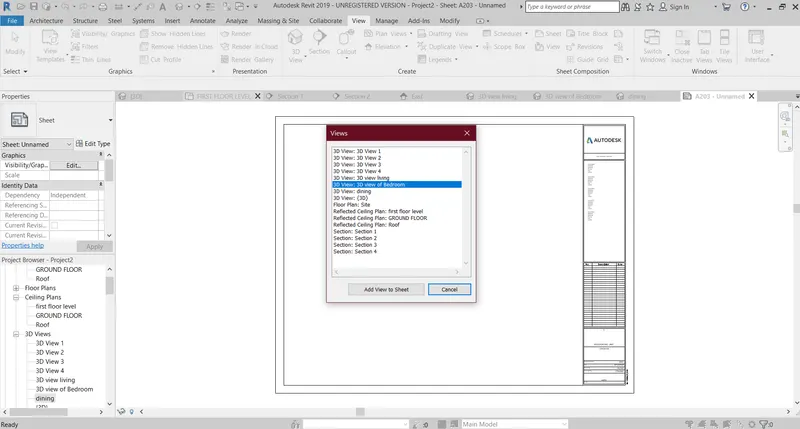
STEP-3:Select View in the View toolbar. A View dialouge box appear ,Select the view and add to the Sheet .
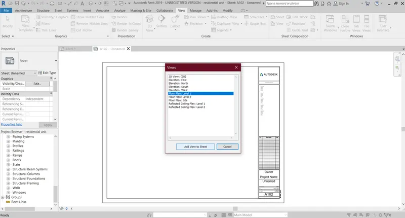
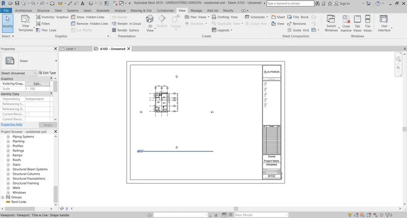
STEP-4:Now you can also change the View scale in the properties.
STEP-5:We can also change the Sheetname ,Sheetnumber,checked by,projectname in properties and by double cliking in the sheet directly we can rename .
RESULT:
The sheet template is Created and paramters are adjusted and different views are added in the sheet success fully.
6) Using the elevation tab create the elevation views, looking at your building from East, North, South and West
AIM:To Create the Elevation views of EAST,NORTH,SOUTH AND WEST of our model by Using the Elevation tab.
TOOLSUSED:
Open
View
Elevation
PROCEDURE:
STEP-1:Open the revit softtware and select the open and open the file that you have created later.
STEP-2:select the view tab >Elevation>elevation .
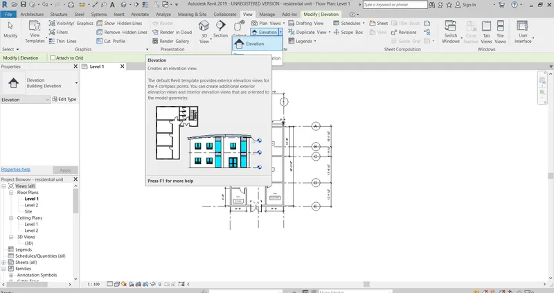
step-3:Place the elevation in the direction You need like south, north,east,west
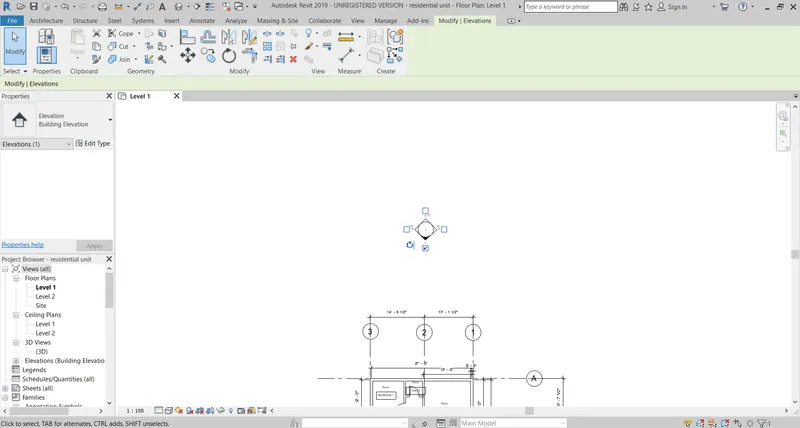
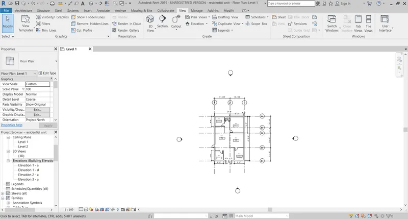
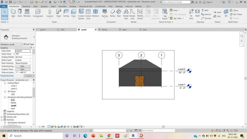
STEP-4:Now, we can see the different Elevations in properties browser as Ellevation1-a....Rename them as North,East,South,West.
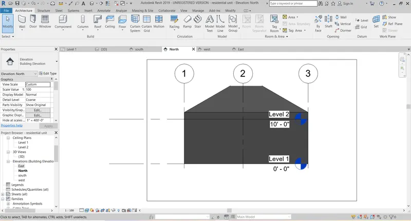
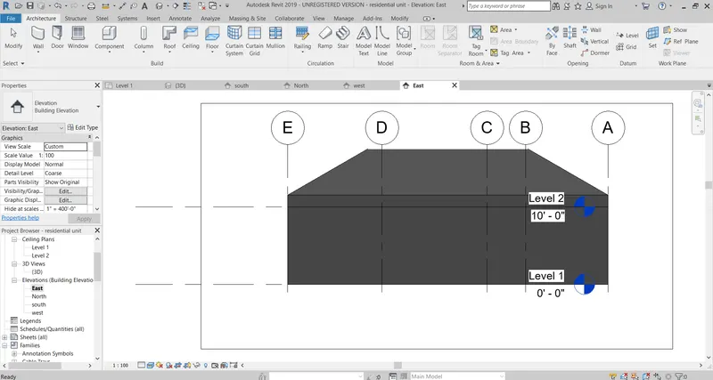
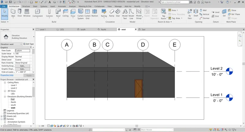
Step-5:Now ,View the different Elevataions.
NORTH VIEW
EAST VIEW;
WEST VIEW:
SOUTH VIEW:
RESULT:
The Different Elevation views are created by using elevation tab and viewed them successfully.
7) Produce section cut through each room either cutting across longitudinally or in a transverse direction.
AIM:To Produce the Section Views for each room Either cutting across longitudinally or in transverse direction.
TOOLSUSED:
view
open
section
properties Browser
PROCEDURE:
STEP-1:Open the revit and select the previous created file.
step-2:Go to View tab and select the section.
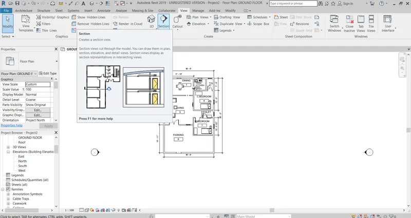
STEP-3:Draw the horizontal or traverse lines in which direction and where you need the section view
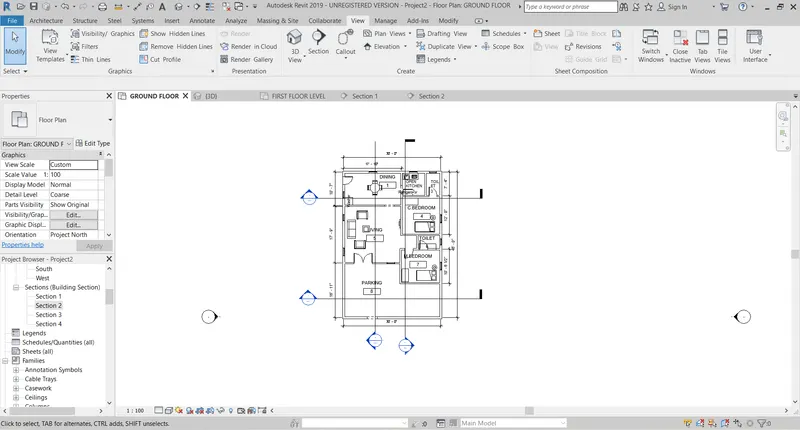
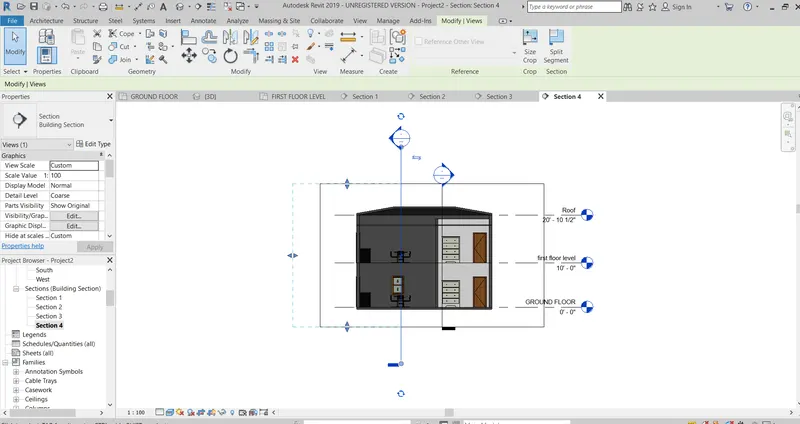
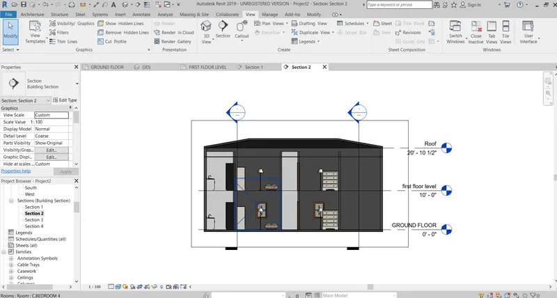
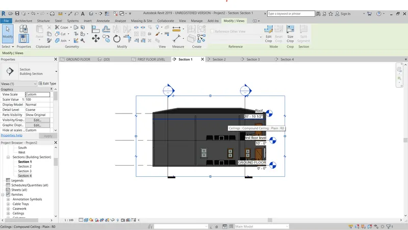
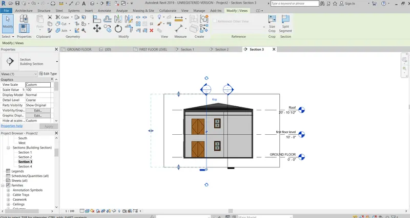
Step-4:Now, The different sections created we can view them in properties browser in section category.If you Want to rename that section we can rename them.
SECTION-4:
SECTION-2:
SECTION-1:
Section-3;
RESULT:
The different sections in (Longitudinal &Transverse direction )for the layout is created and viewed them successfully.
8) Classify the views , Plan Views, Section Views and Elevation views to either Design or Documentation category using Properties browser
AIM:To classify the views like plan views,Section views,Elevation views to either Design or Documentation category using Properties browser.
TOOLSUSED:
Open
viewtab
sheet
load
PROCEDURE:
STEP-1:Open the Revit software, and open the previous file which you have saved.
STEP-2:Go to View tab >Sheet.
STEP-3:Now ,A dialogue box of newsheet appears ,click on load and the sheet of dimensions which you need.
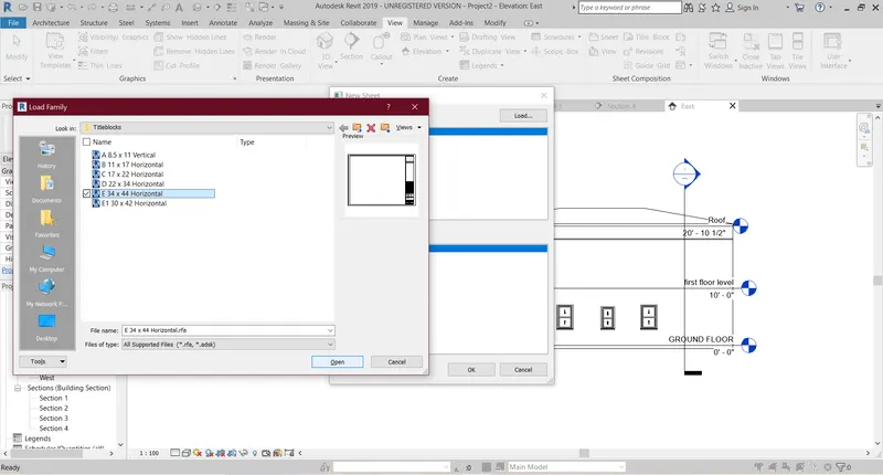
STEP-4:Select the view and load the views which you want to insert in the sheet.Click add to view sheet.
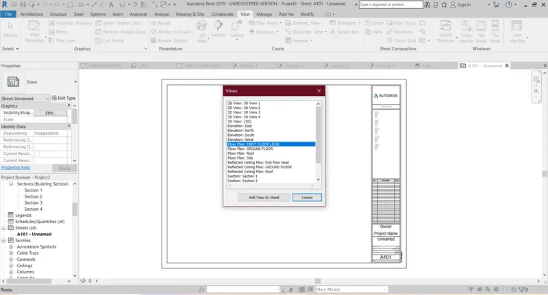
STEP-5:In properties browser we will have view scale change that to the required scale you needed.
STEP-6: Fill the all deatailings like projectname,sheet issued in the sheet by double clicking or we can chage in propertieS AND CLICK APPLY.
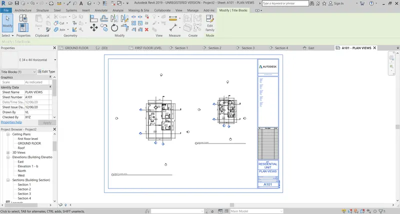
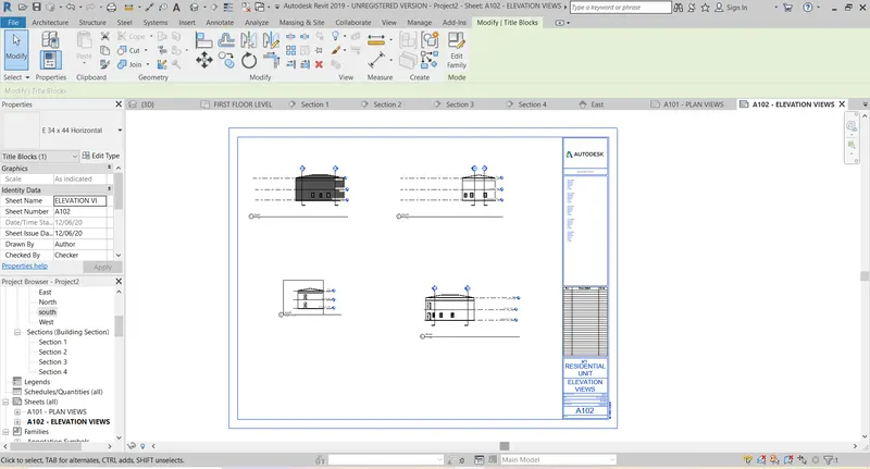
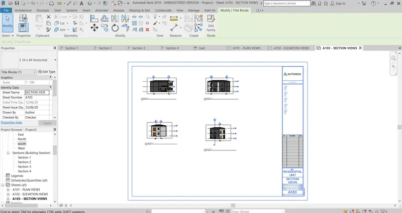
STEP-7:Insert all the section views and elevation views in the sheet.we can rename the sheet by selecting sheets category in the properties browser and doule clicking on it.
RESULT:
The planviews,section views, elevation views are classified and placed in the sheets and they renamed successfully .
9) Using the sheet template produced create multiple sheets as follows
a. A 101 – Ground Floor Architecture Plan
b. A 102- First Floor Architecture Plan
c. A 103- Roof Plan
d. S 101- Ground Floor Structural Plan
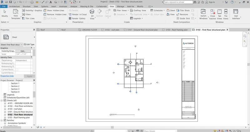
e. S 102 – First Floor Structural Plan
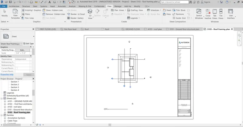
f. S 103- Roof Framing Plan
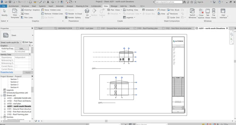
g. A-201 – North South Elevations
h. A-202- East West Elevations
Add additional sheets based on the sections created in your revit file
AIM:To Create multiple sheets by using adding the sheets.
TOOLSUSED:
View tab
sheet
properties browser
PROCEDURE:
STEP-1:open the revit software and select the file> open the previous created file.
STEP-2:make sure that that file must consists of the all the elevations,Groundplan,Firstfloor plan.
STEP-3:Select the Viewtab>sheet.
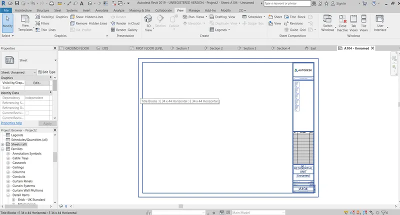
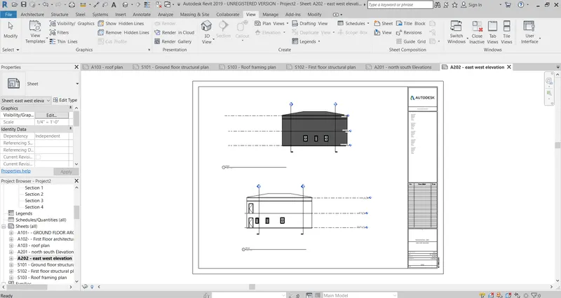
STEP-4:select the view and add the Ground floor view Architectural to the sheet.And rename the sheet by double clicking on the view name in the sheet category.edit all the details like sheetname,issued date in the sheet.
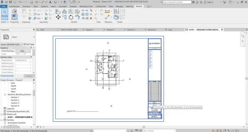
STEP-5:Like the step-4 add the First floor to the sheet.
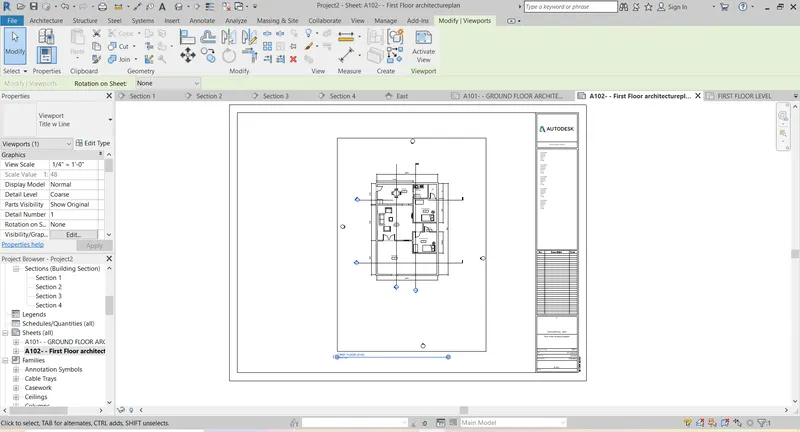
Step-6:Do the same for the creating a sheet for roof plan.
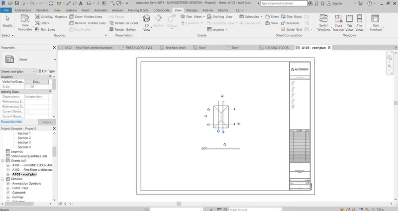
STEP-6 :Create the structural plan for both first floor and Ground floor by selecting view>Planviews>structural plan .
STEP-7:select the View > sheets > load> ok.Go to properties browser>sheets and right click and rename the sheet as required i.e.,Ground floor structural plan.
STEP-8:Select the view and add the view to the sheet.and adujust to the scale of required by changing the view scale in the properties.
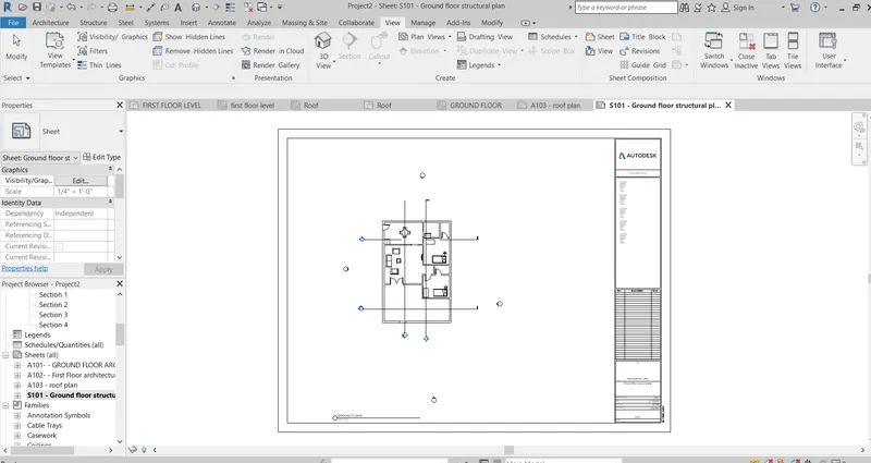
STEP-9:Do the same process like STEP-7 and STEP-8 for creating all the remaining sheets.
S 102 – First Floor Structural Plan
S 103- Roof Framing Plan
A-201 – North South Elevations
. A-202- East West Elevation
RESULT:
The different views are inserted in the sheet template and named them and new sheet templates are added successfully.
10) Create a camera specific view or a 3D view in each room ( living, dining, bed room ) . Based on the views create new set of sheets starting A-501 (you can add as many sheets after , 502, 503.. n)to place the 3D view images.Produce the sheets as a part of project drafting.
AIM:To Create a Camera specific view for each room (living,Dinning,Bedroom) and creating the new set of sheets to place the 3D view images.
TOOLSUSED:
open
View
3D view
sheet
PROCEDURE:
STEP-1:Open the Revit software
STEP-2: Open the previous model that u saved.
STEP-3:select the view and select the 3D view >camera and place the camera in the place where you need the views like bed room ,living ,dining.
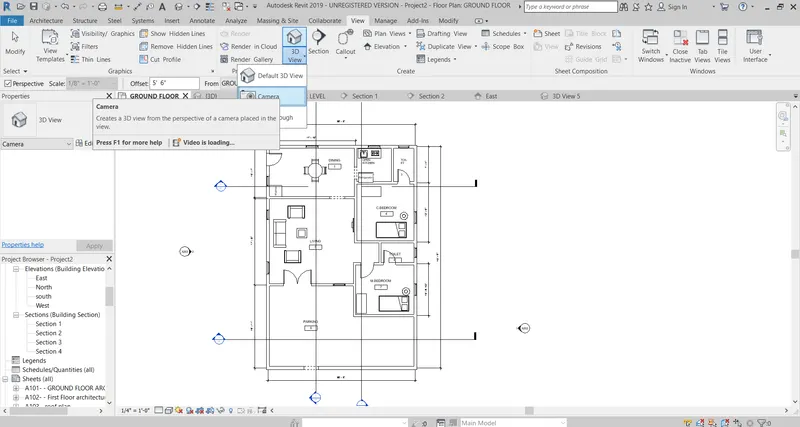
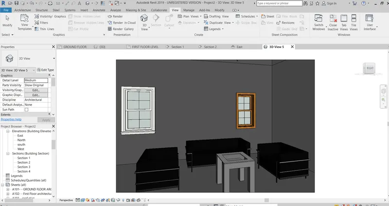
STEP-4:Now you can view the camera view of living hall.you can rename the view name in the properties browser>3D view and rightclick on the view you want to change > rename.
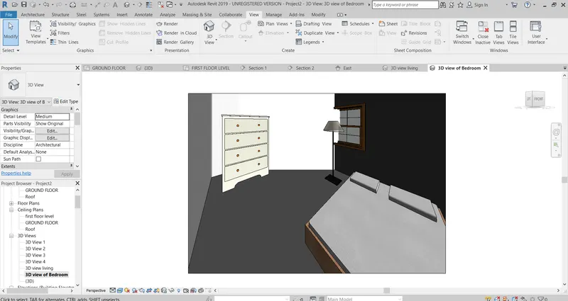
Camera view of Bedroom
Camera view of dining
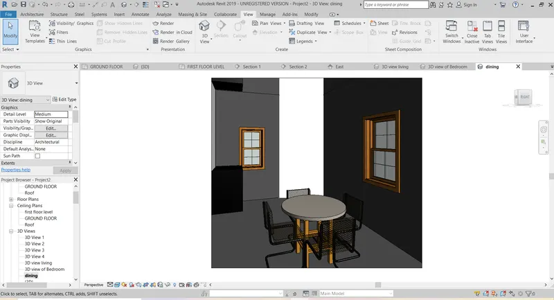
STEP-4:select the view and click sheet to create a sheet template.Place the views in the sheet by selecting the view and add view to sheet
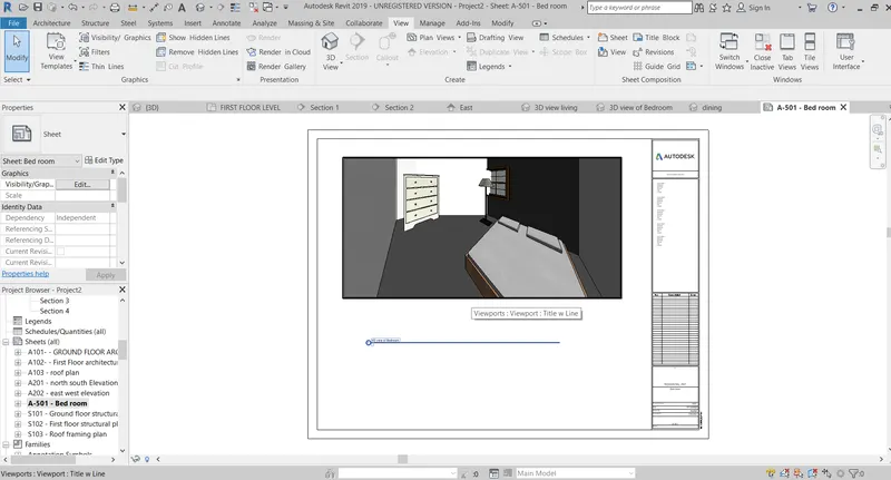
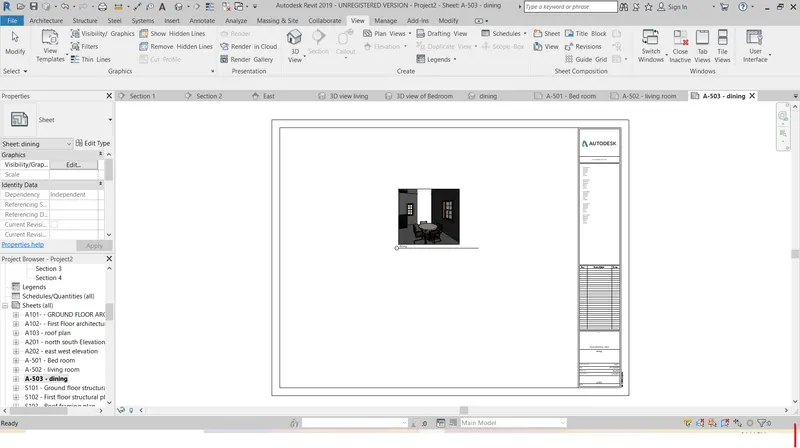
Step-5: Rename the sheet name by seecting the properties browser>sheets >right click and rename as A-501 Bedroom.
STEP-6:Place all the views in the view sheet by using the step-4 and step-5 procedures.
SHEET OF A-502 LIVING ROOM
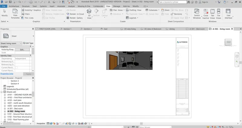
SHEET OF A-503 DINING
RESULT:
The specific camera views are created to different rooms and they are placed in the sheets duccessfully.