REVIT_Introduction to REVIT_Week 1
1)
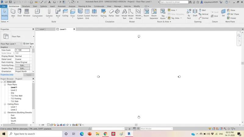
AIM: To create a new project by using the file menu and naming the project .
TOOLS USED:
- FILE
- NEW
PROCEDURE:
1.Firstly ,open the Revit software.
2.click on the File menu which appears on the top left corner.
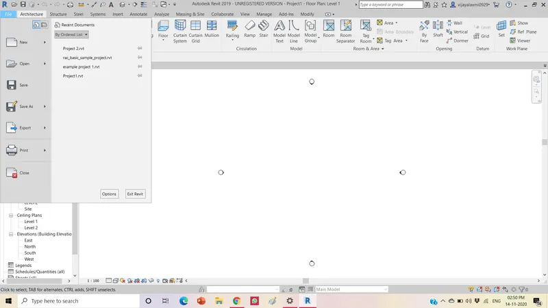
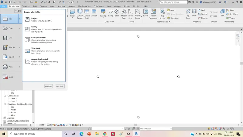
3.click on the New icon.
.
4.Newproject dialogue box will appear,click on the template file.you will be seeing different templates.
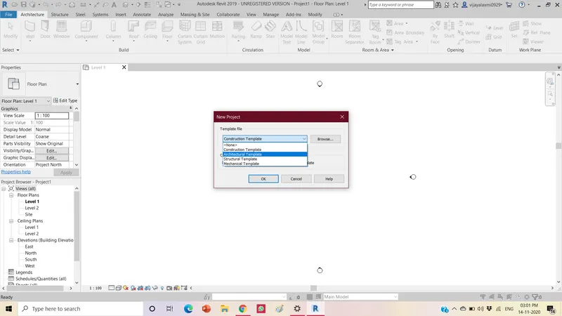
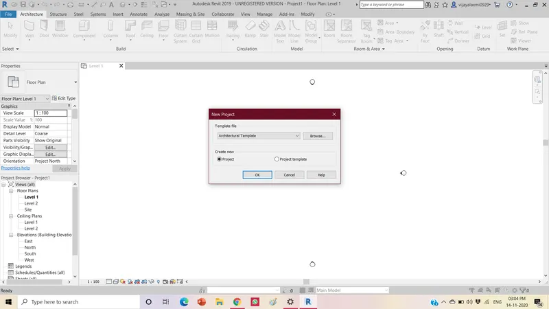
5.click on the Architectural Template and click ok.
.
RESULT:
The new project file of Architectural template is created and named approximately.
2)
AIM: To save the new project file , closing and opening the project by using the icons of the file toolbar.
TOOLS USED :
- FILE
- SAVEAS
- OPEN
- CLOSE
- PROJECT
PROCEDURE:
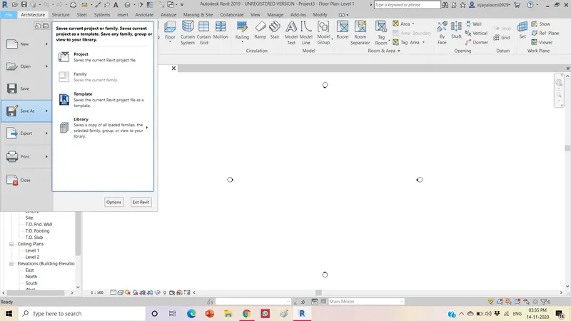
1. Click on the file toolbar.
2. click on the SaveAs icon .
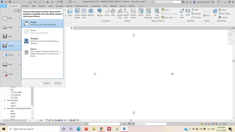
3. click on the project ,we will find the dialouge box.
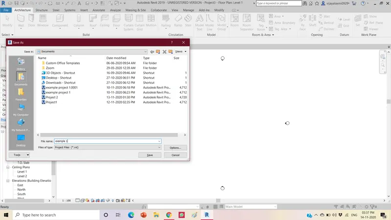
4.Enter the file name and select the desired loctaion that you want to save it.
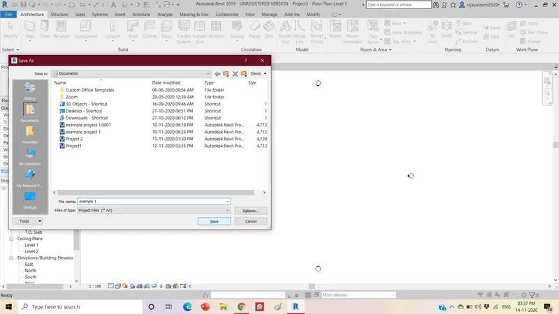
5.click on the save option.
6.Click on the file menu and click the close icon.
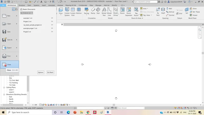
7.click on file menu, and click the open icon the dialogue box appears ,select the file you wank to open and click open.
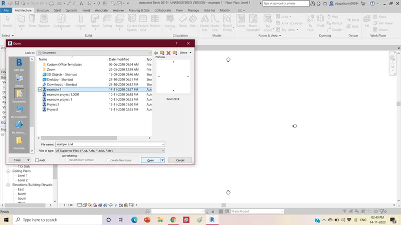
RESULT:
A new project file with the name given is saved.
The file is closed by using close icon and opened by using open icon.
3)
AIM: To create a rectangular layout of wall of about 40'-0'x35'-0'. From the Architectural/structural toolbar familiraize to options to draw a wall.
TOOLS USED:
- ARCHITECTURE
- WALL
- PLACEWALL
- RECTANGLE
PROCEDURE:
1.Firstly,open the Revit .
2.click on Architectural toolbar.we will find the wall icon click it.
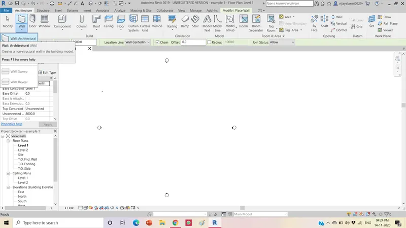
3.select the desired wall:Architecture.
4.A toolbar Popups ,Go to Place wall.
5.select the line or rectangle .
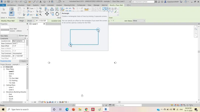
6.Draw the rectangle by specifying the dimesions of 40'-0''x35'-0.
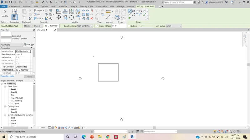
RESULT:
The rectangle layout of dimensions 40'x35' is successfully created.
4)
AIM:To add dimesions to the layout by using Aligned option from the Annotate toolbar.
TOOLS UESD:
- ANNOTATE
- ALLIGNED
PROCEDURE:
1.Click on Annotate toolbar .
2.click on the aligned icon .
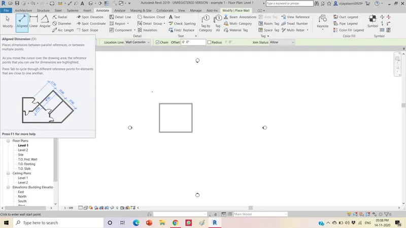
3. select the two reference points and click enter.
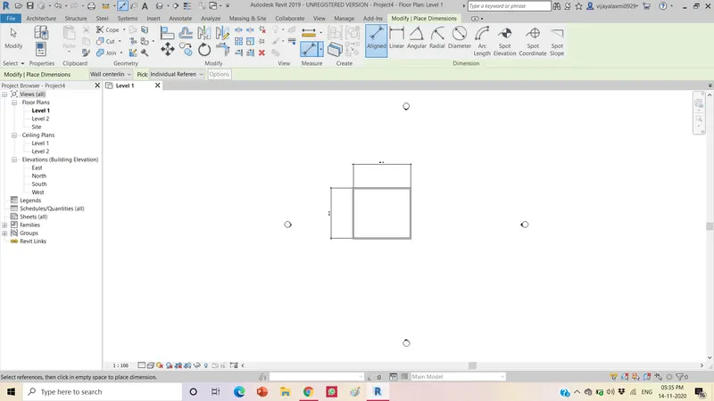
4.The dimensions are displayed.
RESULT:
The rectangle layout with the dimensions is displayed.
5)
AIM:To switch to` different types of walls by using the properties browser.
TOOLS USED:
- PROPERTIES
- EDIT TYPE
PROCEDURE:
1.Select any wall of the drawn figure .
2. click on the properties which appears on th left side .
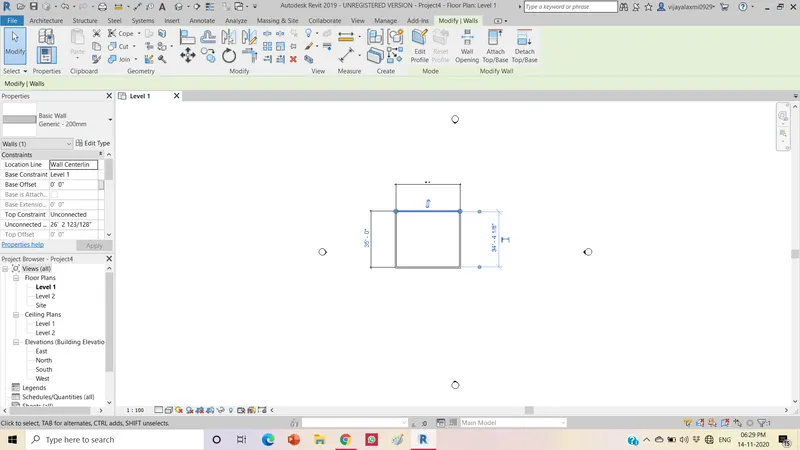
3.click on edit type ,a dialouge box will appear or we can directly select the walltypes by clicking on dropdown menu.
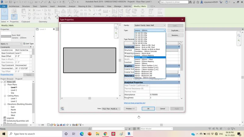
4.Select the type of wall required and click ok.
RESULT:
The wall changed into the wall type which we selected by using properties browser.
6)
AIM:To create a 3D view from the view toolbar and saving the view with the appropriate name.
TOOLS USED:
- VIEW
- PROPERTIES PALATTE
- 3D DEFAULT VIEW
PROCEDURE:
1.create a model.
2.click on the view toolbar.
3.select the 3d view icon and select the DEFAULT 3D VIEW .
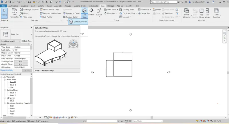
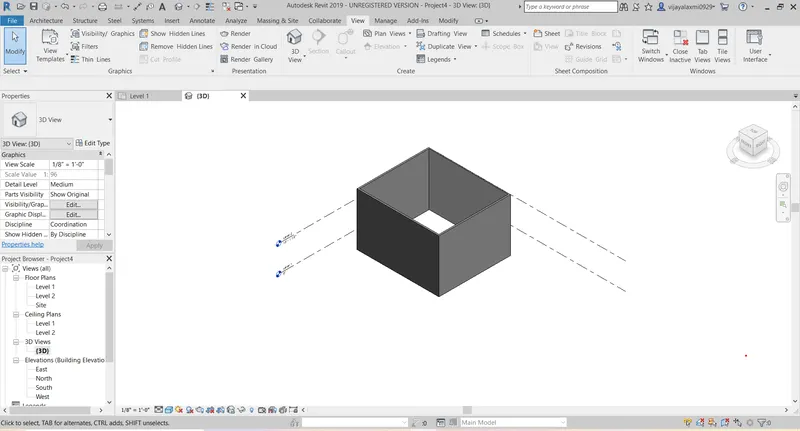
5.Then,in properties we will find identity data in that click on view name .
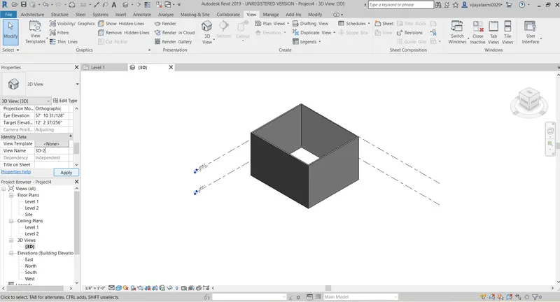
6. change the name and click on Apply .
RESULT:
The 3D view is created successfully and the name of the view is changed as 3D-2.
7)
AIM: To navigate through the 3D model using the view cube.orbit/pan through the model layout created.
TOOLS USED:
- view
- 3d view
- view cube
- Navigation Wheel
PROCEDURE:
1.Create a 3D view model .
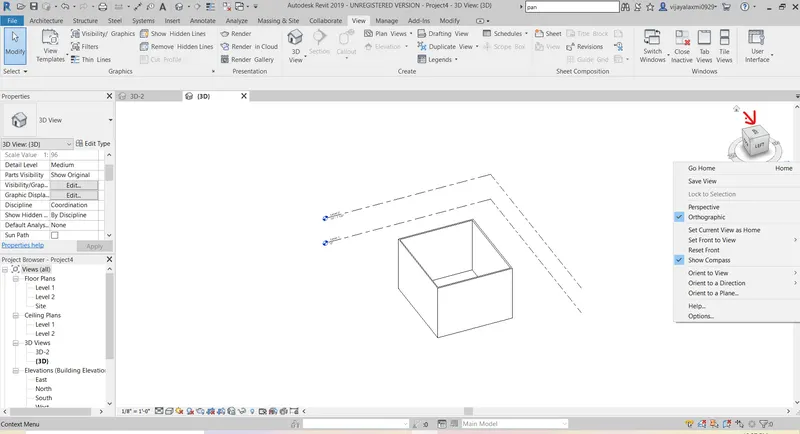
2.click on the viewcube which is at to right corner
3.click and drag to switch between standard and isometric views of the model
.
4. Click on orbit in the full Navigation wheel to view the model in different angles.
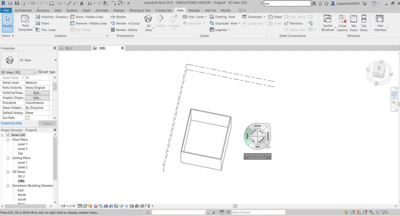
5.click on the pan and drag to move the model.
RESULT:
The 3D model is successfully viewed in different viewpoints by viewcube and moved by using pan.
8)
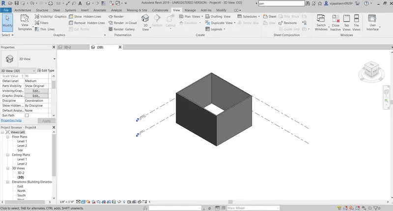
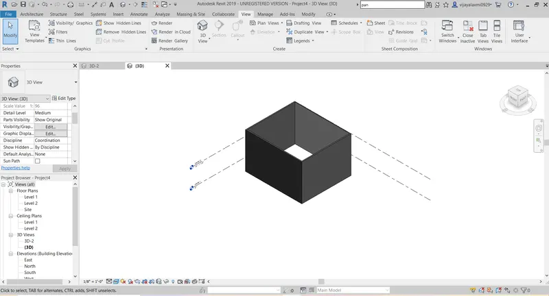
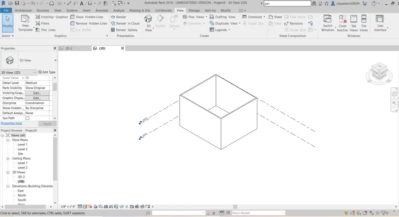
AIM:To switch the model to shaded ,realistic,hiddenlines options by using the visibility setting option below.
TOOLS USED:
- View
- 3D view
- VISUAL STYLE
- GRAPHIC DISPLAY OPTIONS
PROCEDURE:
1.create a 3D model .
2.Click the view toolbar we will find the cuboid symbol at the bottom click it.
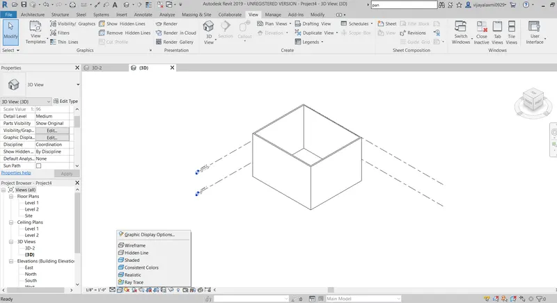
3.The graphical display option box appears.
4.select the realistic,Shaded,Hidden lines.
RESULT:
Now we can successfully switch the model in to different visuals.
9)
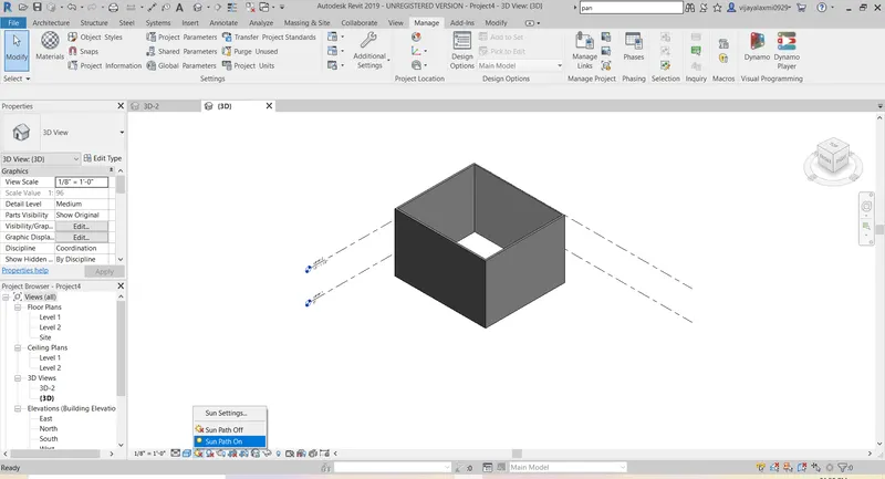
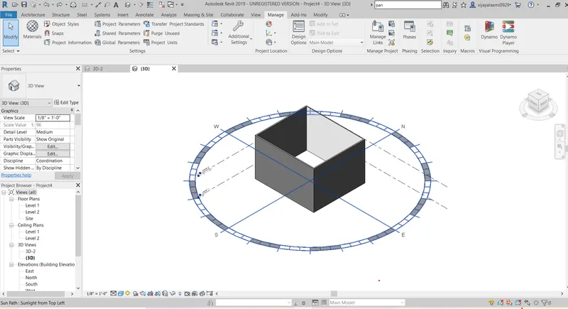
AIM:To turn the sun path on and off to view shadings in the layout created .
TOOLS USED:
- Manage toolbar
- Additional settings
PROCEDURE:
1.Create a 3D model.
2.select the sun which is at the bottom left .you will view the sunsettings in that we will find the sunpath on and sunpath off options.
or
we can go to the manage toolbar and then ,select additional settings option .
RESULT:
Now successfully we can on and off the sunpath to the model.
10)
AIM:To enter Project settings,project name,Project issue Date by using the Manage Toolbar.
TOOLS USED:
- Manage Toolbar
- Project information
PROCEDURE:
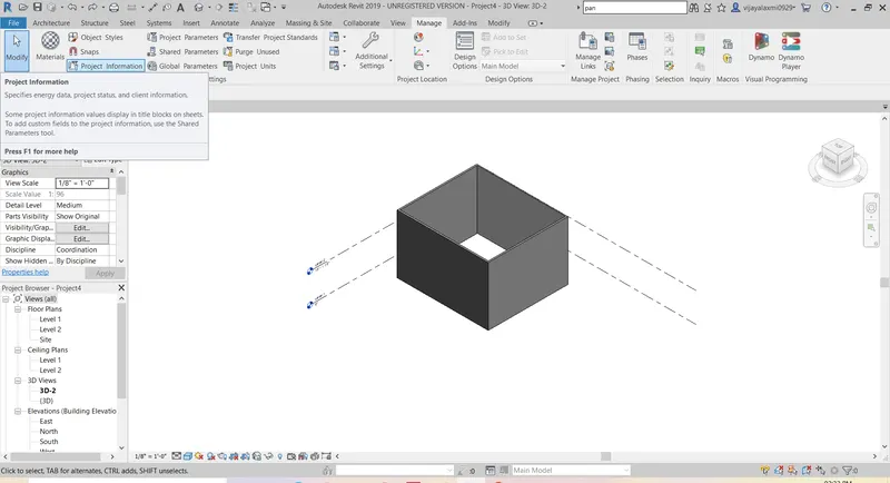
1.Go to manage toolbar.
2.click on the project information icon.
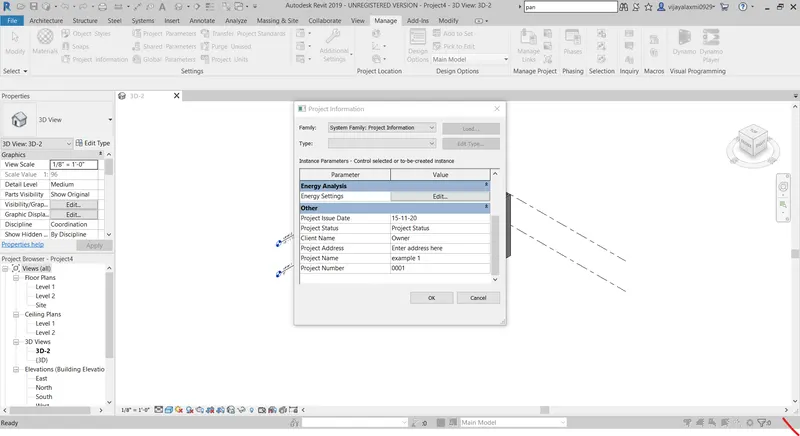
3.A dialogue box appears. In that we can view the project status ,project issue date , project settings enter them and Click on ok.
RESULT:
The project name ,Project issue date and project settings are successfully done by using project information icon in manage toolbar.
11) What is the Analyze toolbar used in Revit? How it is beneficial for design and modeling.
- Analyse toolbar helps us to analyse on our structuralbuilding.It consists of differrent options like BONDARY CONDITION which helps us to Define line ,point,area condition
in the analytical model and verifies the boundary condition family types are loaded and assignedin the structural setting menu.
- By using the LOADS icon we can add and edit the loads to the anlytical model .
- CONSISTENCY option verifies the analytical and physical model for consistency.
- HEATING AND COOLING LOADS prepare load analysis report based on the exsisting building model.
- Create the energy analytical model and generate design options and potential performances outcomes with insight.
- specifies the suitable geographic location for the project and examine the warning and makes changes to the model as needed to rectify.
12)What are the links that Revit supports to be linked to the model?
- Link Revit:we can Link another revit model to the current model.
- Link IFC: It links an IFC file to the current project to reference its information for additional design works.If we make any changes in the original IFC file reflects in the current project.
- LinkCAD : Link Autocad file to the current project . Later any changes made in CAD file reflects in the project.
- DWF Markup:Links marked-up DWF file into a revit project so we can see the marksup on corresponding sheets.
- Manage Links:we can also link Revit files and CAD files to the current project.
- Load Family:It Loads a Revit family into the current file.
- Import CAD: It Imports data or 3D geometry from other CAD programs to a Revit project or family.
13)Why do you need the Collaborate tab in Revit? How it supports modeling and its efficiency
- Colllabrate tab is used combine the work of different disiplanes in the same project.
- Revit offers multiple features to different disciplanes of engineering such as architectural ,structural,mechanical,
plumbing it helps to work independently on each disciplane .To complete the project it is necessary to view alltogether so this
collaborate is used to combine all the work to achive progress.
- It enables collabration so team members can work on a model simultaneously.YOu can edit and sync a model in the cloud,
on a local area network or on a Wide area network.