REVIT_Creation of Basic Drawing_Week 2
ANS-1
BIM is a acronym for building information modeling .It is process in which AEC i.e architecture,engineering,construction professionals collabrate on the planning,design and construction of a building within one 3D model. It is supported by various tools and technologies.BIM was invoked by autodesk and we can say that autodesk helps us in achieving BIM.It is a very effective and advanced software plays very important role in drafing and planning sofwares.it is basically classified into
- COORDINATION
- COMPUTATION
COORDINATION- In this mechanical,architectural,electrical and constructional people can work together which meansn multiple people can perform multiple tasks in the same software with cooperation to each other.this helps in time saving and gives better efficieny and accuracy.
COMPUTATION-It is process of calculating and computing that takes place in software .It means it includes both arithmetical and non arithmetical steps and which follows a well defined model.
BENEFITS:
1-With this we can produce complete representation of the project.
2-With BIM we can avoid a lot of errors.
3-With this one can work more efficiently and increase designer productivity.
4-This enables a faster product design process i.e 45% faster compared to 2D CAD tools.
5-With interactive 3D models it helps user to create realistic designs and one can visualize the end product .
6-improves in scheduling.
ANS 2-
We understood as following:
CATEGORIES-A category controls the organization,visibility,graphical representations and scheduling options of families within revit project such as door,window.
FAMILIES-It is a grouping of 2D and 3D information that serves to represent a building element.For example:single door,double door.
ELEMENTS-There are different types of elements .this is used for specific representation of family defined by distinct parametric,graphical and documentation characteristics which makes it unique from other types in family.For example:36"X84"-full vision
INSTANCE:These are the items which will be available after installing the families.
This is how represntation takes place from category to instance,
DOOR-----SINGLE DOOR------36"X84"-FULL VISION------REPRESENTATION AS DOOR.
AIM:To go to insert tab and select a category, pick a family and select elements as well as instances required and place them in revit.
TOOLS REQUIRED:
- INSERT TAB
- LOAD FAMILY
- FILE NAME
- OPEN
PROCEDURE:
1-Firstly we need to open revit and select architectual template.
2-Then we need to click on insert menu.
3-There select load family which is present at right side.
4-Then a load family dialog box appears.
5.Select the desired component from the family dialog box.
6-Then click on ok.
7-As we selected windows component now we need to go to window option from architectural menu.
8.There select the object loaded from load family and drag it to place it need to be placed.
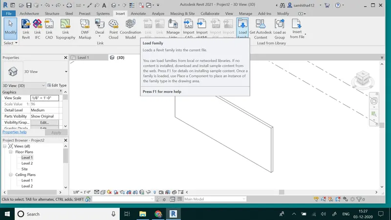
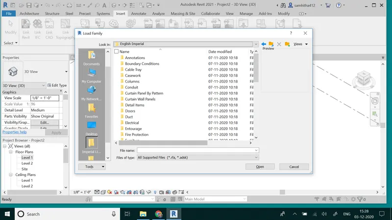
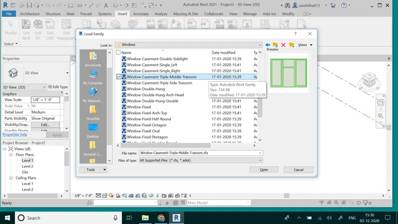
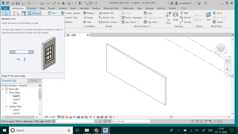
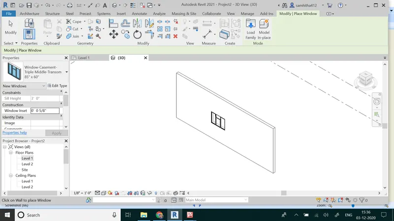
RESULT: With the help of the above steps we can use the families and the components in our project.
ANS 3-
AIM: To open a project file with architectural template. Save the file with appropriate name.Set up the project units. Complete the project information and set up maximum backups for project file upto 3.
TOOLS REQUIRED:
- NEW
- SAVE AS
- MANAGE
- PROJECT UNITS
- PROJECT INFORMATION
PROCEDURE:
1-After opening revit click on new option there select on architectural template.
2-Now click on manage menu
3-There click on project units present at left corner present in settings box.
4-Setup the project units to imperial/metric based as required.
6-Then click on project information present in manage menu in settings box beside project units and then fill up the details.
7-To save a file we need to click on filemenu and select save as option,then give appropriate name in dialog box appeared .
8-Thereafter while saving the project in save as dialog box click on file options there set maximum backup to 3 and click ok.
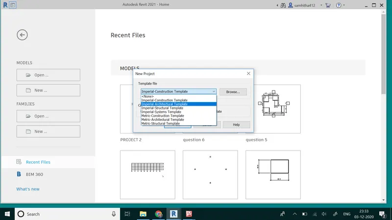
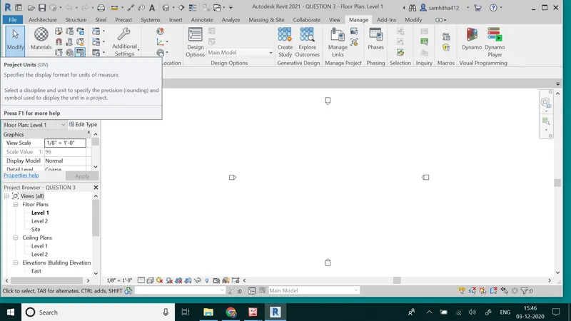
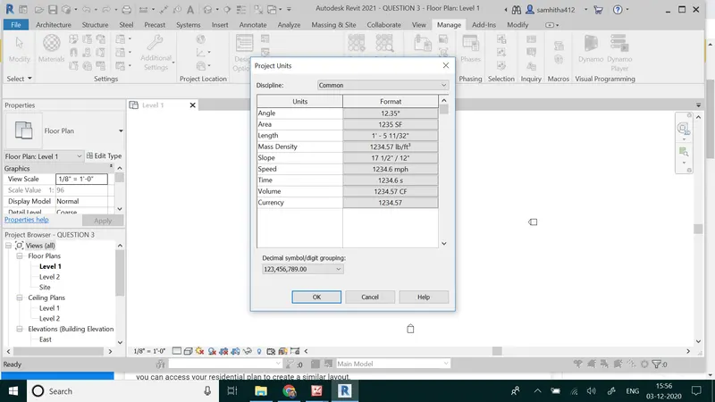
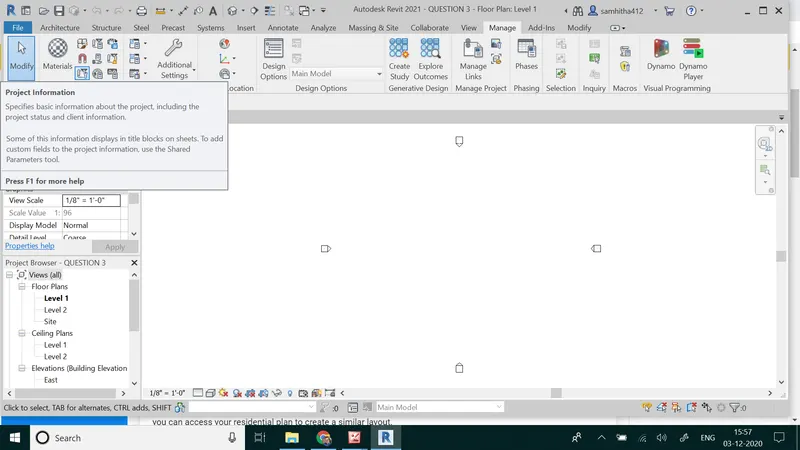
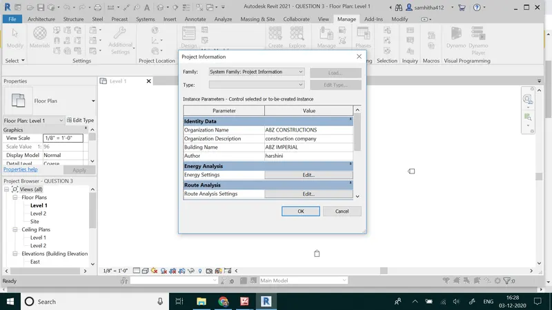
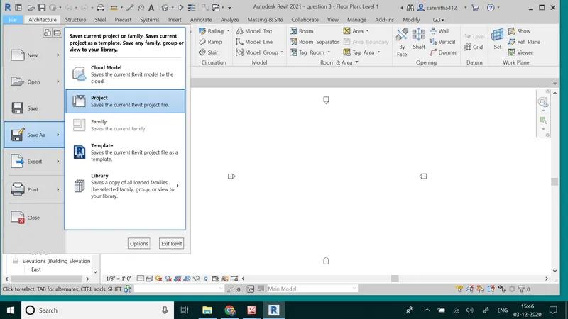
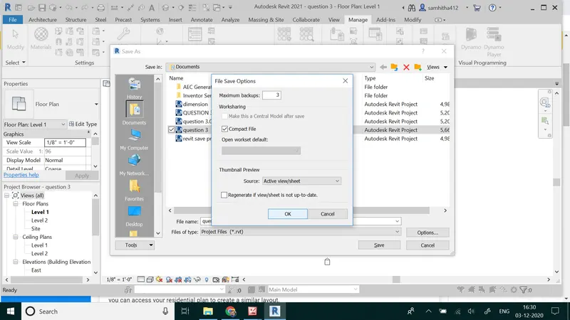
RESULT: We can a open a project in architectural template and save it with a appropriate name having 3 backups of the project as following. We can change the projects units and fill in the project information with above steps.
ANS 4 -
AIM:
Given to create the following levels.
- ground floor@ 0'
- first floor@ 10'
- second floor @ 20'
- roof @ 30'
Transverse grids A,B,C,D,E @ 10' spacing.
Longitudinal grids 1 to 10 @20' spacing.
TOOLS USED:
- ARCHITECTURE TAB
- GRID
- LEVELS
PROCEDURE:
1-Firstly we need to select architecture tab which is present at left corner.
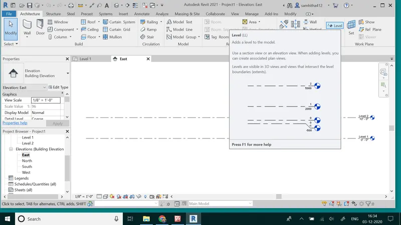
2-Then click on east option in elevation which is present in properties.
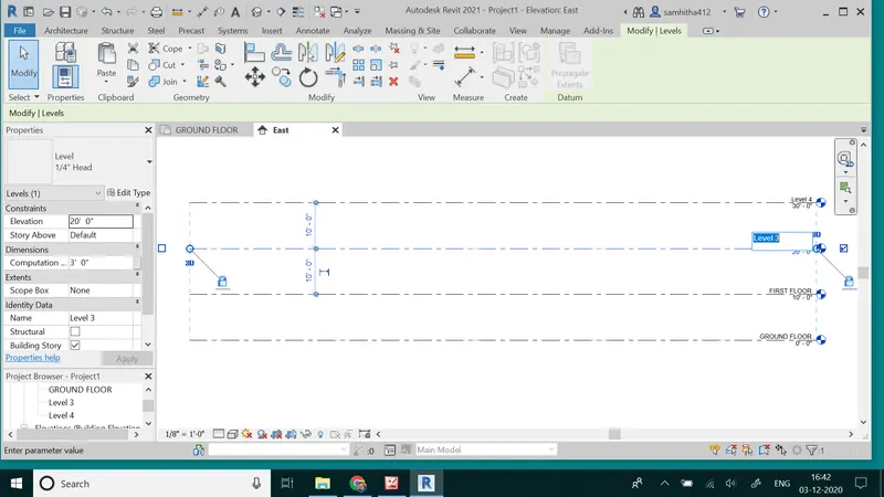
3-we then get elevated view of levels,we have to rename them as required and place them in equidistance as mentioned .
4-We require 4 levels that is ground,first,second,roof as given in question so we need to add levels from datum in architecture tab with spacing of 10' in between each.
5-After placed new level we just need to name them.
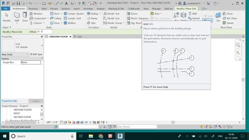
6-Now we need to select ground floor under floor plans.
7-Select grid option under datum from the architectural menu and start placing them.
8-first we need to draw 5 horizontal grid lines of placing 10' space between each and name them A,B,C,D,E accordingly from top to bottom
9-then we need to place 10 vertical grid lines along with spacing of 20' in between them and name them from 1-10 from right to left respectively.
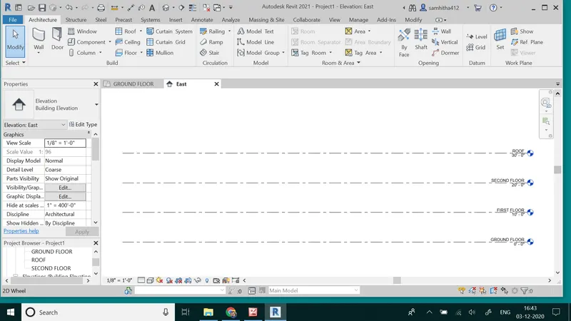
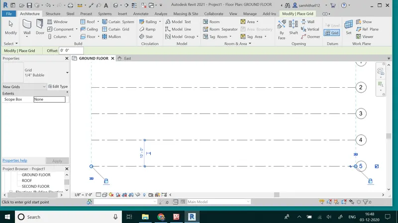
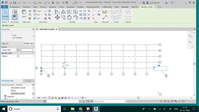
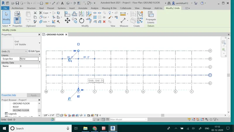
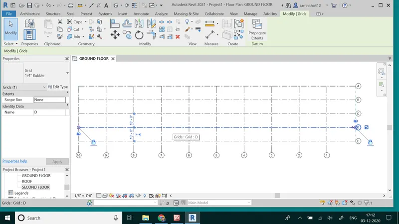
RESULT: Therefore we represented the required grounf floor,first floor,seconf floor and roof at the heights od 10',20',30' along with grids of horizontal and vertical grid lines 1-10.
ANS 5-
AIM: To 3D model a residential house,to create a conceptual layout of the residential unit.
TOOLS REQUIRED:
- ARCHITECTURE
- WALL
- VIEW
- DEFAULT 3D VIEW
PROCEDURE:
1-Open revit and select architectural template and click on ok.
2-Now select wall tool from architectural menu and then place them in drawing space.
3-Firstly we need to have a layout of drawing.
4-According to that we need to place walls in required dimension.
5-After completion of closed model as per layout we need to click on view menu.
6-There we need to select default 3d view in 3d view option.
7- The required layout appears in 3d view.
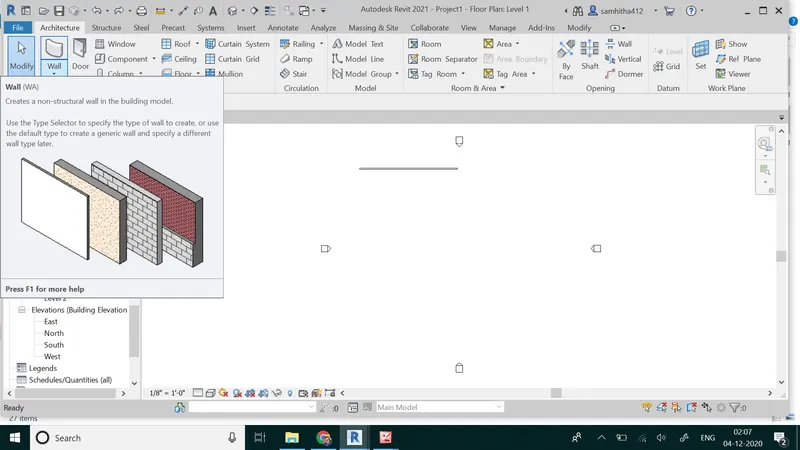
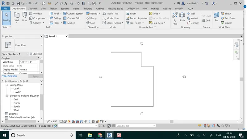
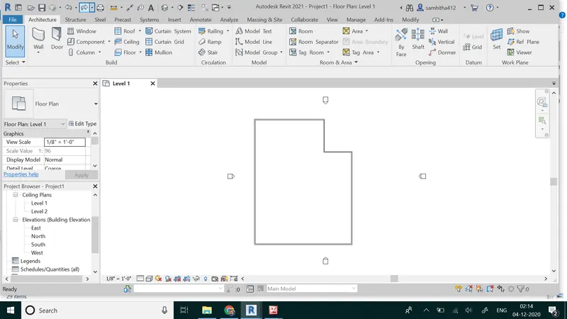
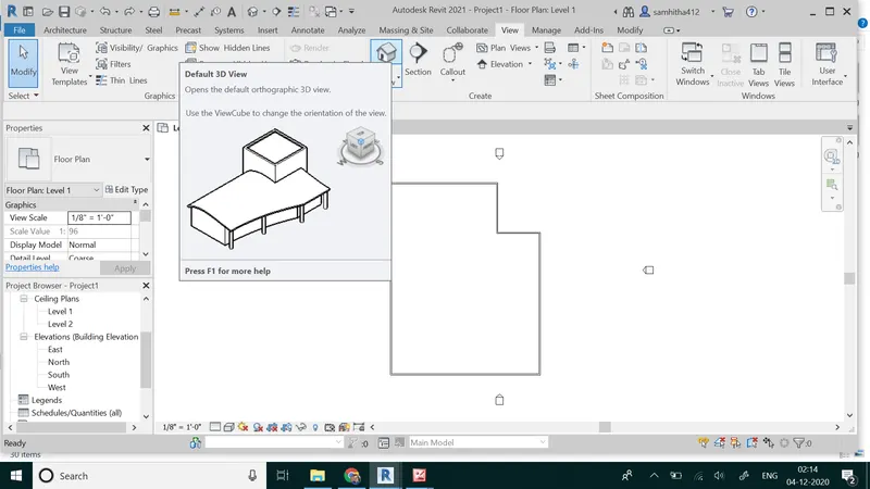
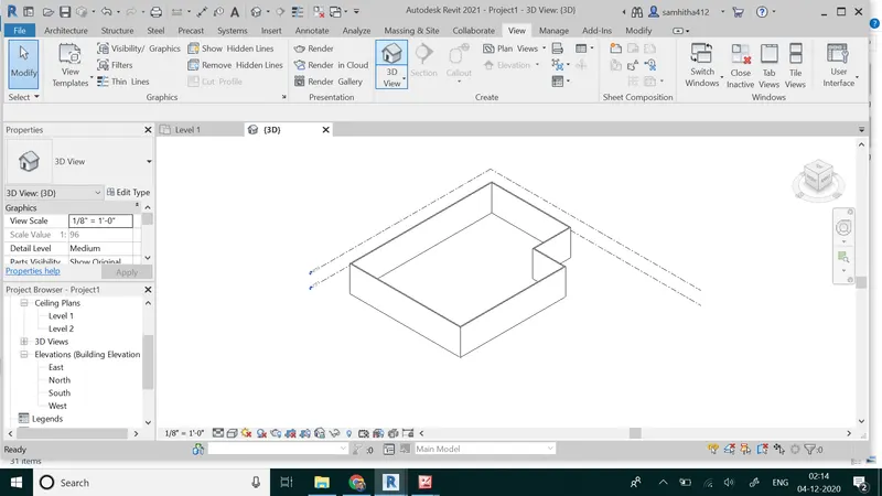
RESULT: Thus by following above steps we have drawn our required layout in 3D view.
ANS 6-
AIM: To include details such as dimension of room ,add components to the residential unit to the layour created.
TOOLS REQUIRED:
- INSERT
- LOAD FAMILY
- ARCHITECTURE
- WINDOW
- DOOR
- VIEW
- DEFAULT 3D VIEW
- WALL
PROCEDURE:
1-After completing the layout with four closed sides of walls as per dimensions.
2-Then we need to use wall option from architecture menu to place the inner walls of rooms in layout.
3-After completion of layout with rooms we need to load required components from insert menu from load family.
4-To mark dimensions we need to click on the annotate menu there we need to select aligned option.
5-Then click on view menu and select default 3D view to convert the project in 3D view.
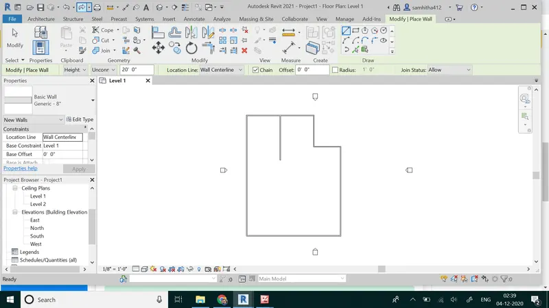
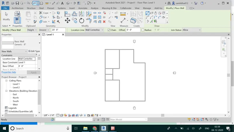
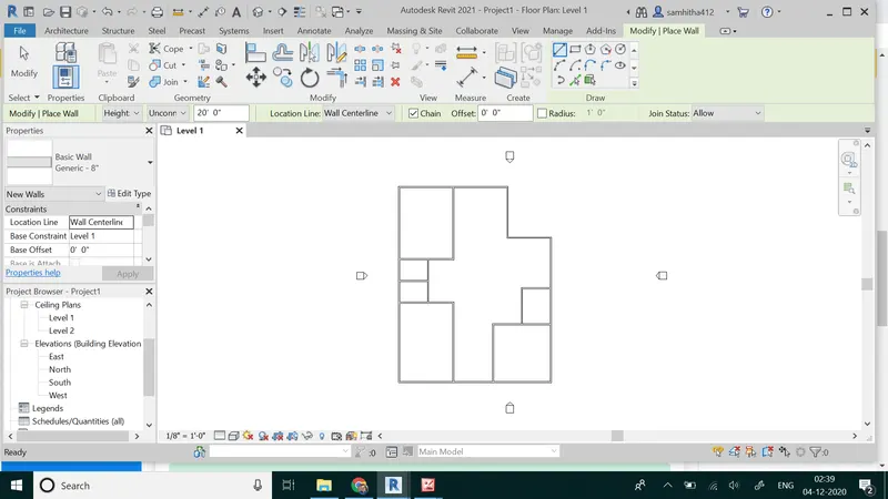
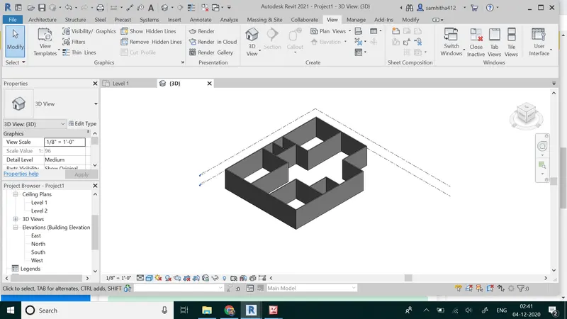
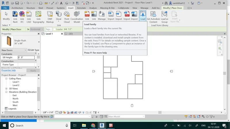
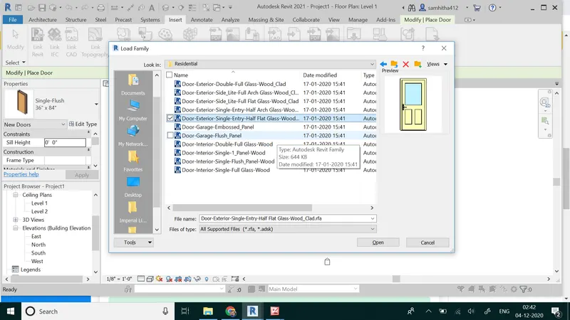
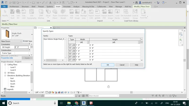
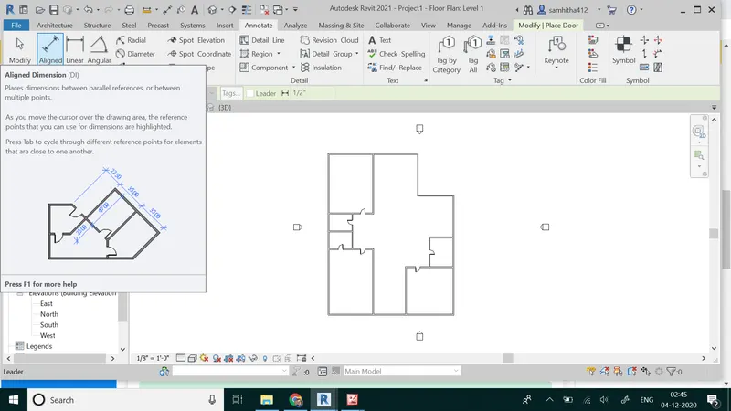
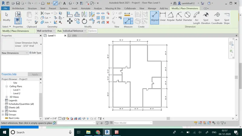
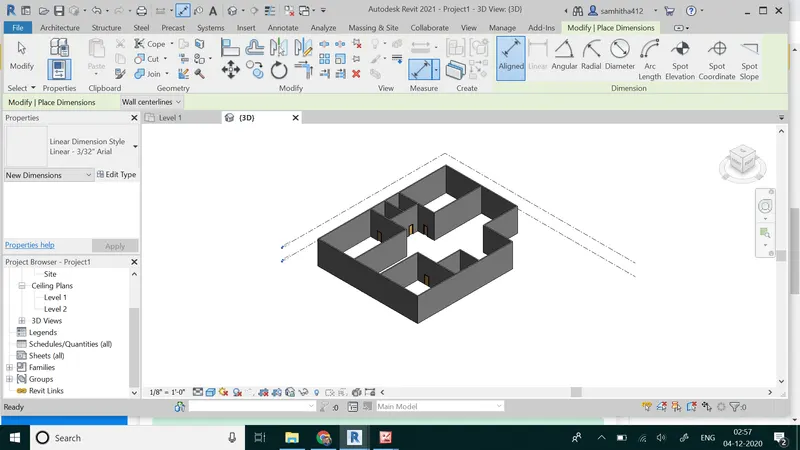
RESULT: By following above steps we successfully created a layout of the residential unit with included details such as dimensions and loaded components to be added.
ANS 7-
AIM: To add components to the layout project like doors,windows,tables,chairs,couch,bed,lamps from insert menu.
TOOLS REQUIRED:
- INSERT
- LOAD FAMILY
- VIEW
- ARCHITECTURE
- DOORS
- WINDOWS
- COMPONENTS
- BED
- DINING TABLE
PROCEDURE:
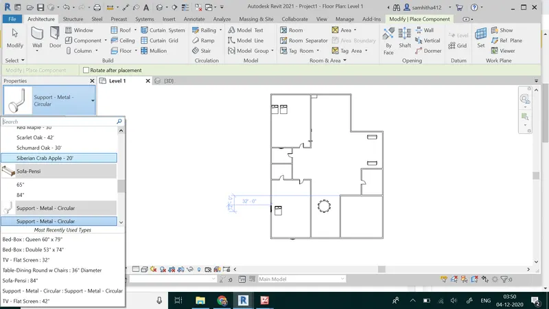
1-As we have completed the inner walls and dimensioning now we have to start placing the required components.
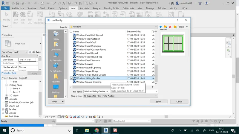
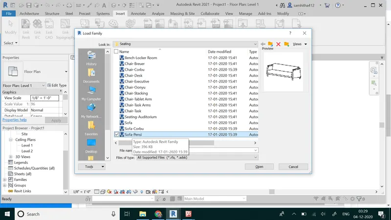
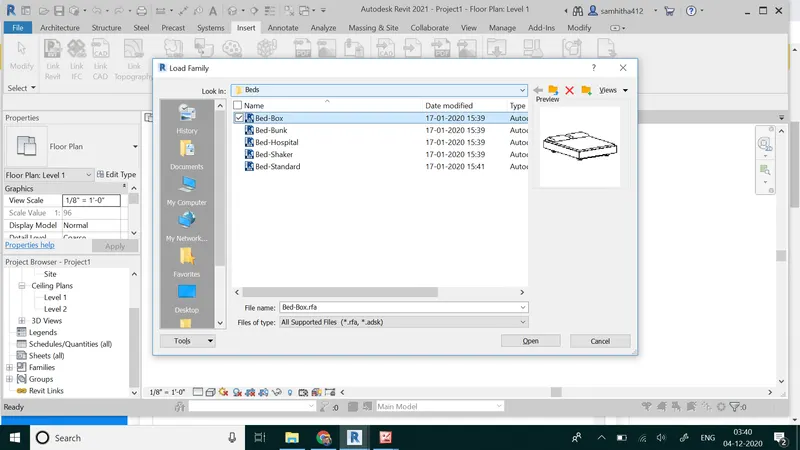
2-From insert menu we have click on load family .
3-In the dialog box appeared there are various components through them we need to load required components like doors,and other components like sofa,beds ,table etc.
4-After placing them successfully we need to click on default 3D view from view menu so that we can have 3D view.
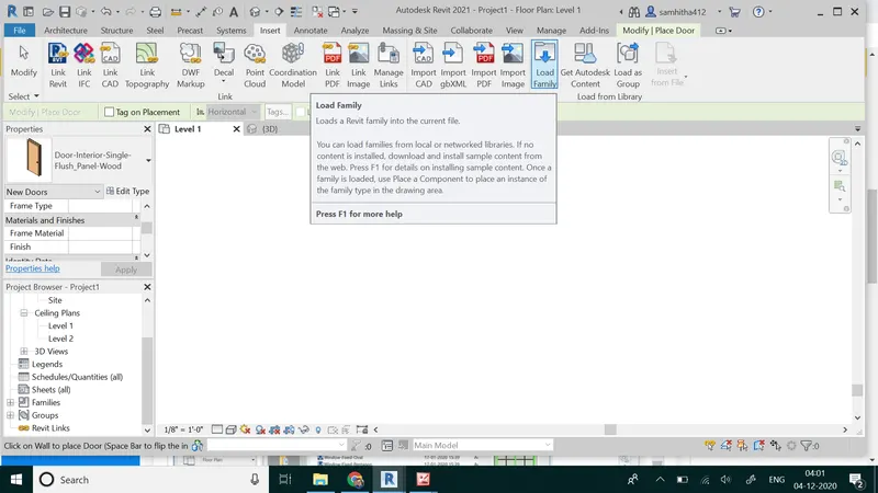
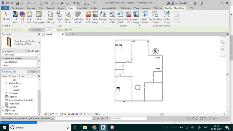
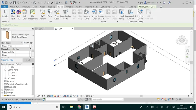
RESULT: By following above steps we successfully placed required components to the project layout .