Reinforcement detailing of Columns from ETABS output
AIM & INTRODUCTIION :
AIM :
To provide details of longitudinal reinforcement for the two columns 3A and 3B, from foundation to terrace level then run the analysis and design the RCC moment resisting frame.
INTRODUCTION :
- In E-TABS the stuctural members such as beams, columns and slabs can be created and analysed its bending moment and shear force.
- We can Run the Concrete Frame Design fo the created structure to provide required both Longitudinal and shear reinforcement bars automatically.
- The values for the created structures can be automatically calculated by E-TABS.
- Here in E-TABS we can know the number of Reinforcement bars should be provided for the concrete structures.
- From Frame design analysis we can see both Top and Bottom reinforcement figures for each beam sections.
- Also we can display concrete frame design result for Shear reinforcement.
- Moreover we can view the concrete beam design information as per IS 456:2000.
- The Design details of the overall structures can also be viewed as Summary, Flexural Details, Shear Details, Envelope.
PROCEDURE :
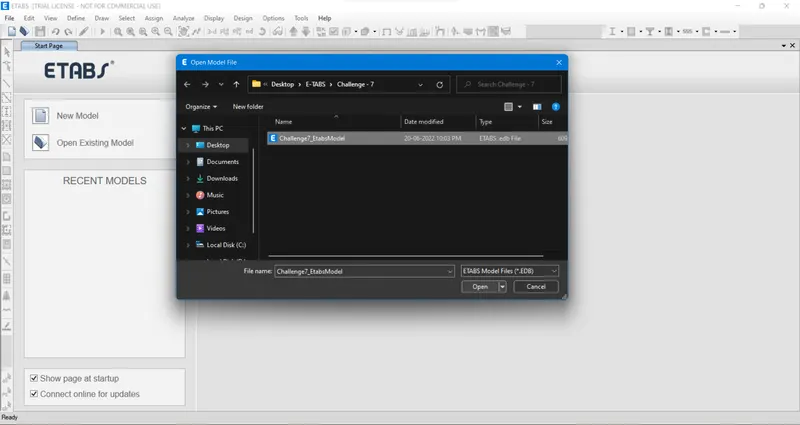
- First open the E-TABS software then click Open Existing Model and open challenge 7 file.
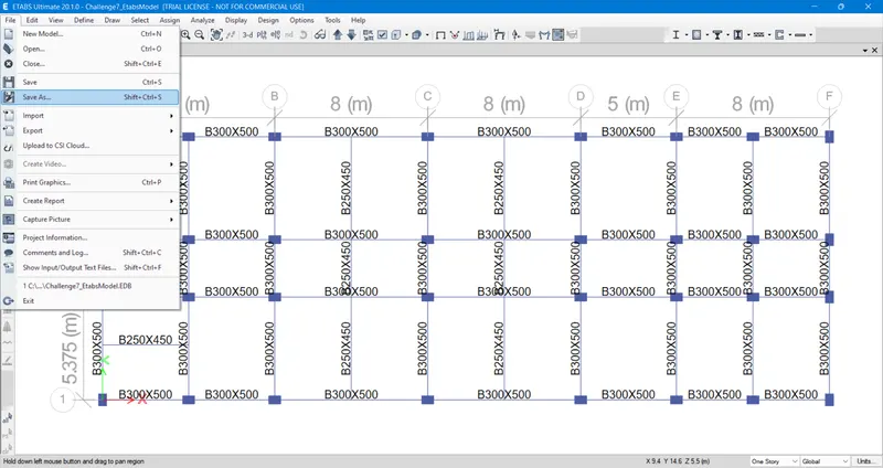
- After opening of the existing file named challenge 7, click File and Save As to save the file as Challenge 9.
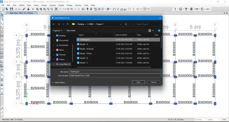
- Then save the file as name of Challenge 9 in appropriate folder and click Save.
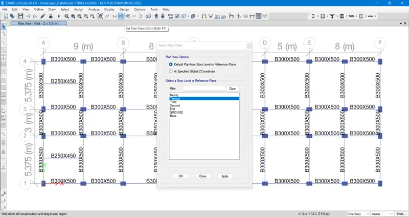
- To view the model from the Terrace level, select Plan option the toolbar and select Terrace from the select Plan View tab and click OK.
- Then select the two columns 3A and 3B as per the question requirement.
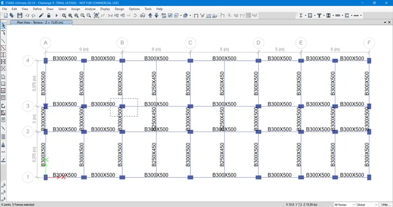
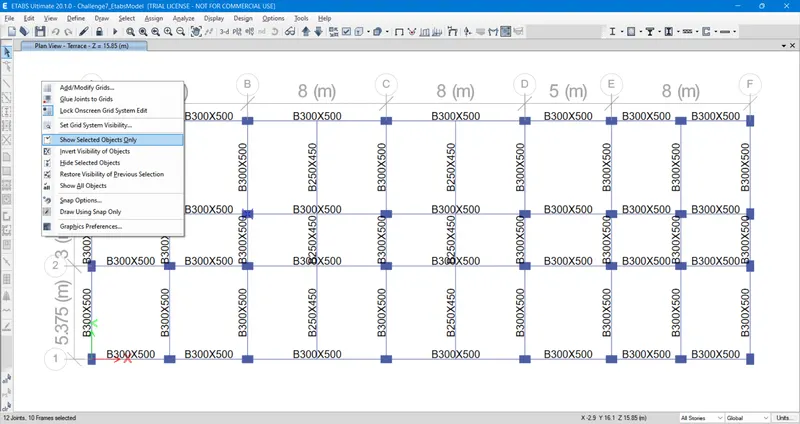
- Then right click on the screen of the workspace and select Show selected objects only to see the selected two columns.
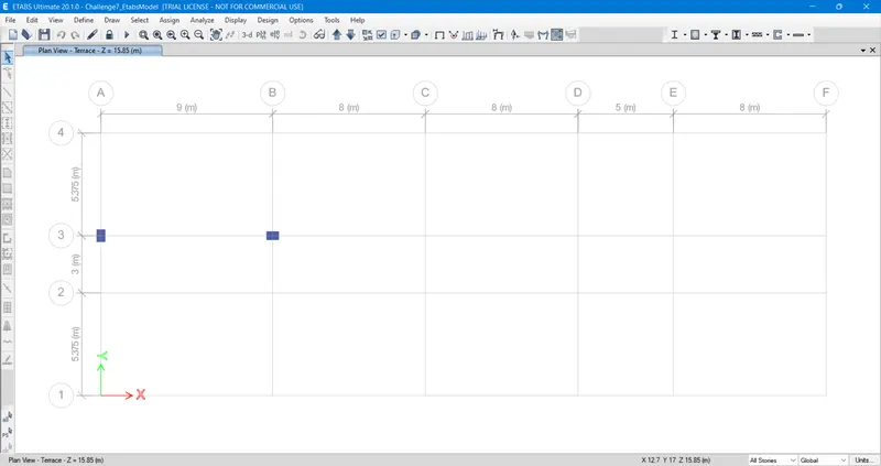
- Here we can see the plan showing only the selected two cloumns 3A and 3B.
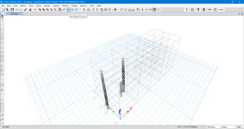
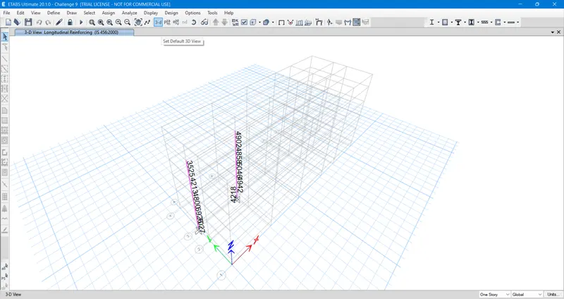
- Click the Set Default 3D view tool in the Toolbar and we can see the 3D view of the columns.
- Now click Run Analysis tool at the Toolbar to start analyse the showing columns.
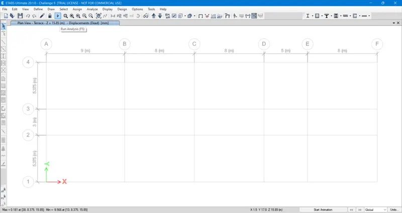
- Followed by click and select Concrete frame design tool at the toolbar above to check .
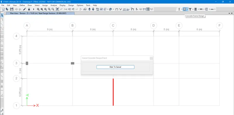
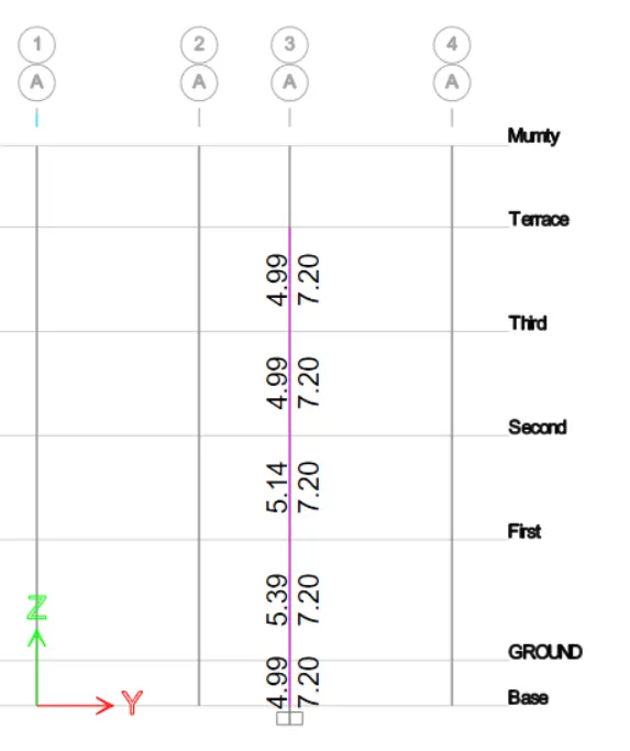
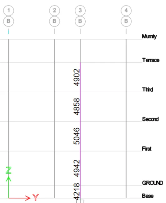
- After the Checking the Concrete frame design, we can see the Longitudinal Reinforcement members of the two columns.
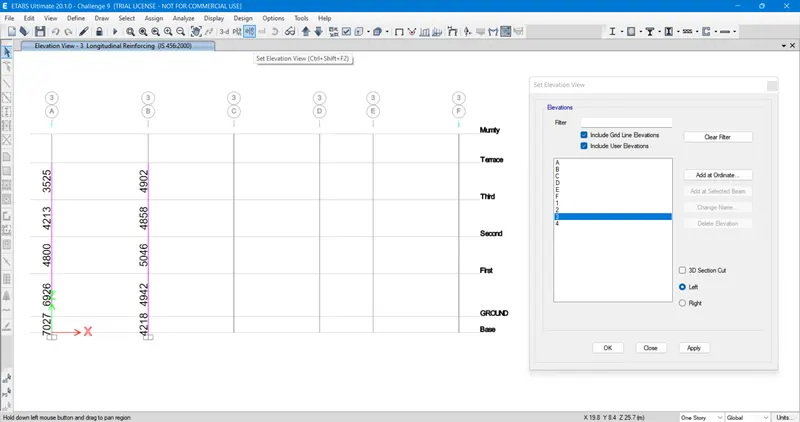
- Click Elevation tool at the toolbar above then select Elevation - 3 and click OK to see it elevation view.
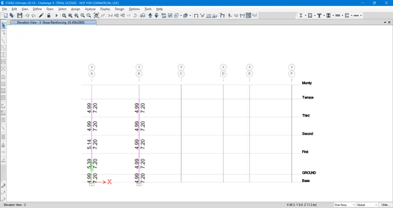
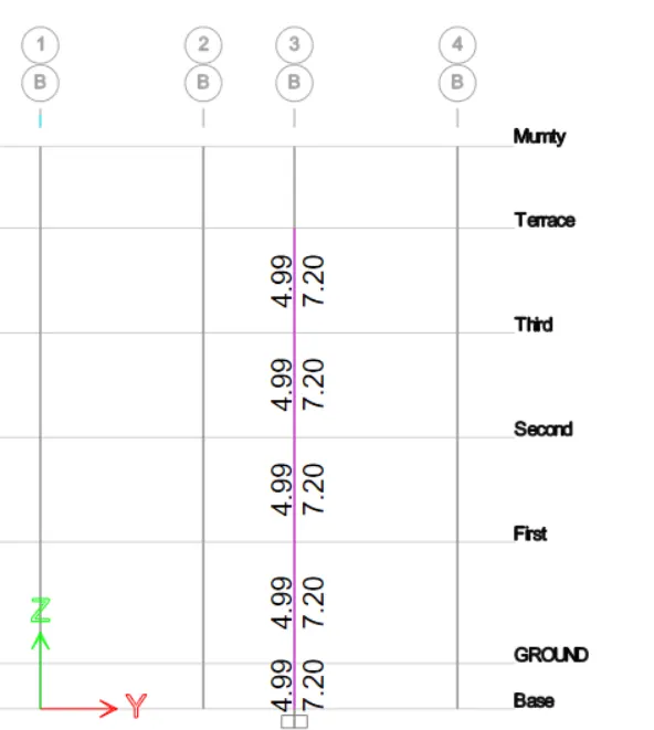
- Now to see the Shear Reinforcement of the Column concrete frame design.
- Then click the downward arrow next to the concrete frame design tool and select Display Design Information.
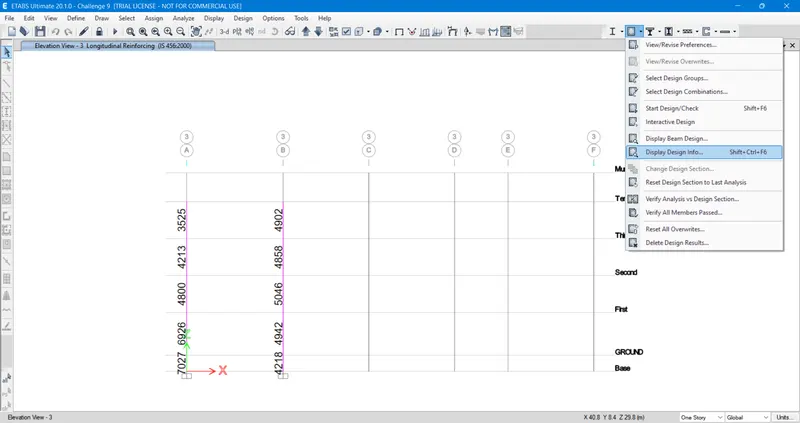
- In the Display Concrete Frame Design Result tab from Design Output select Shear Reinforcement and select OK.
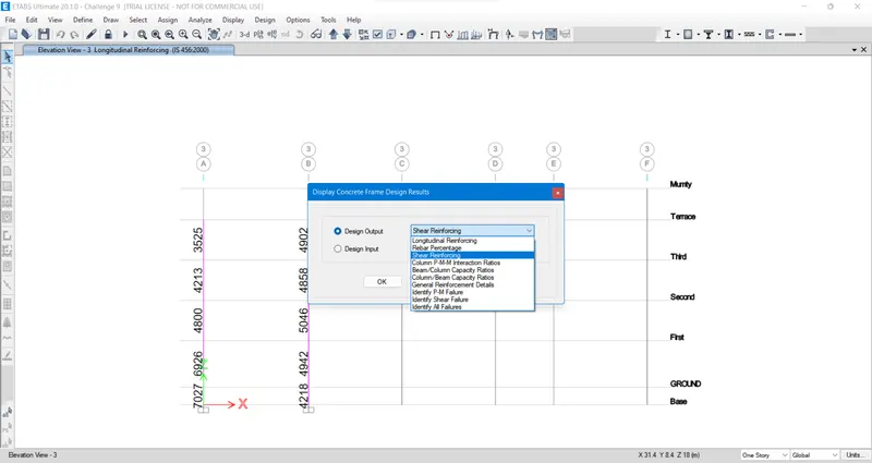
- After selecting and applying the Shear Reinforcement for the columns then we can see the Shear Reinforcement values.
RESULT :
- The ETABS file for a G+4 building is provided. Run the analysis and design the RCC Moment Resisting Frame. The following challenge deals specifically with two columns at the following grid intersections.
1. ) LONGITUDINAL REINFORCEMENT AND SHEAR REINFORCEMENT OF COLUMN AT GRID - 3A FROM ETABS :
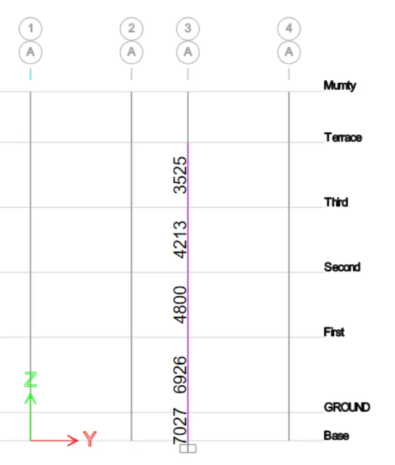
2. ) LONGITUDINAL REINFORCEMENT AND SHEAR REINFORCEMENT OF COLUMN AT GRID - 3B FROM ETABS :
- Provide details of longitudinal reinforcement for the two columns, from foundation to terrace level. Sketch the column cross sectional & elevation details or draft it using autocad software.
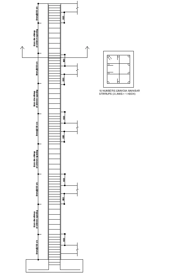
1. CROSS SECTION & ELEVATION DETAILS OF COLUMN - 3A :
2. CROSS SECTION & ELEVATION DETAILS OF COLUMN - 3B :
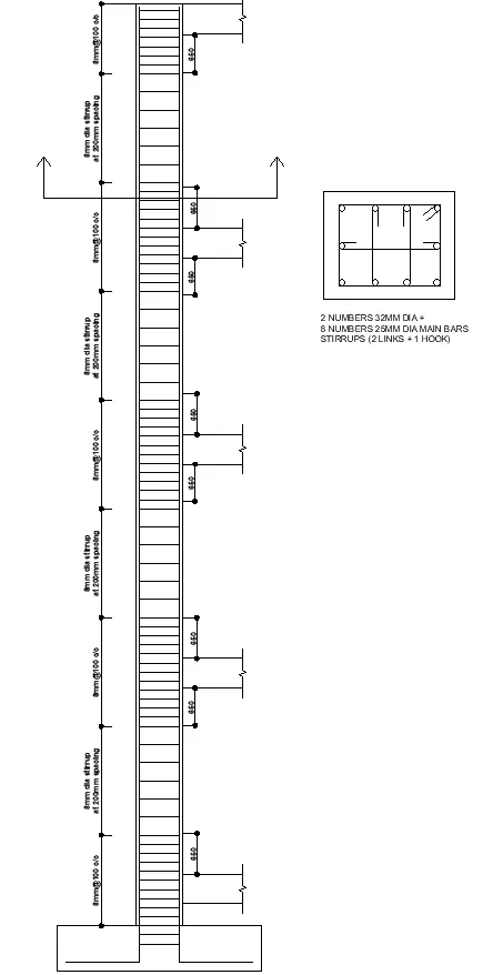
- Show shear reinforcement & lapping details as per special confining reinforcement provision of clause 8.1 of IS 13920 - 2016.
`l_0` IS NOT LESS THAN
a) Larger column dimension.
b) `1/6` of clear span of column. 650mm
c ) 450 mm.
CONFINEMENT SPACING NOT MORE THAN
a) `1/4` of smaller column dimension.
b) 6 times of diameter of column size.
c) 100 mm.
THE AMOUNT OF CONFINEMENT REBAR
`A_s__h` = Maximum of `[[0.18 s_v h f_ck/f_y.(A_g/A_k-1)],[0.05 s_v h f_ck/f_y]]` `169 mm^2`