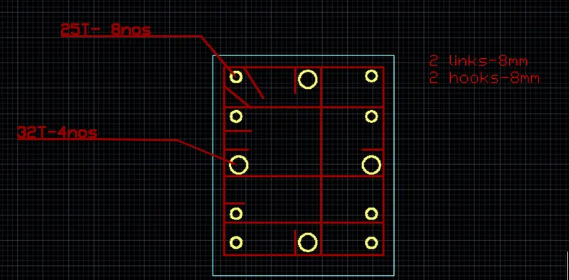
Reinforcement detailing of Columns from ETABS output
AIM: Reinforcement detailing of columns in Etabs 2018.
GIVEN DATA: The ETABS file for a G+4 building is provided. Run the analysis and design of the RCC Moment Resisting Frame.
INTRODUCTION:
QUESTIONS:
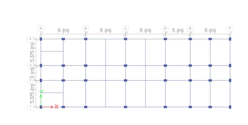
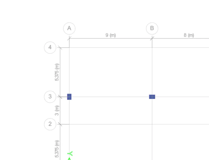
The following challenge deals specifically with two columns at the following grid intersections.
- 3A
- 3B
- Provide details of longitudinal reinforcement for the two columns, from foundation to terrace level. Sketch the column cross-sectional & elevation details or draft it using AutoCAD software.
- Show Ashear reinforcement & lapping details as per the special confining reinforcement provision of clause 8.1 of IS 13920 - 2016.
DETAILING RULES:
- Min. reinforcement for shrinkage and temperature.
- Reinforcement req. for limiting crack width.
- Ultimate limit state design rebar req.
- Ductility rebar req.
Whichever is greater from the above 1-4 should be considered.
- Min. longitudinal reinforcement as per IS 13920 2016, clause 6.2.1; As = 360mm²
- Min. shear reinforcement as per IS 456 2000, clause 26.5.1.6(Assuming 1000mm spacing formula); Asv = 332mm²
- Development length as per IS 456 2000, clause 26.2.1; Ld = 41 x Diameter of the bar
PROCEDURE:
- Open the G+4 ETABS file which was provided by the skill lync in the previous challenge.
- Now select the particular two columns which are to be designed.
- From the view menu, change the view settings to only the selected objects.
- Now open the elevation of the building along the third grid.
- Now, run the program to get the reinforcement details.
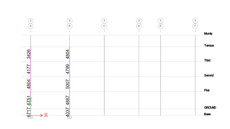
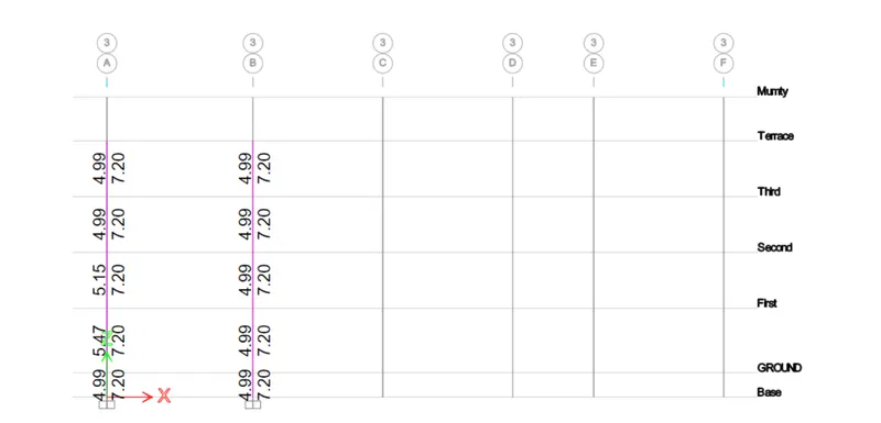
- We can obtain the longitudinal and shear reinforcement requirements for both columns.
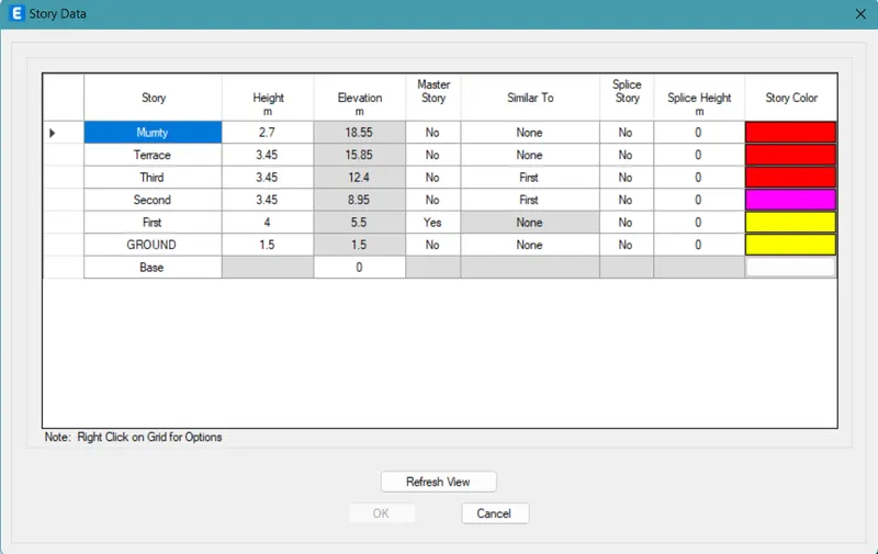
- Please have a look at the below snips for more clarity.
- The sectional plans of the columns are given below in the results section.
SNIPS:
RESULTS:
- The reinforcement details of both the columns are almost very similar to each other. So below is the drawing of the reinforcement details in a sectional view of the column along the 3A and 3B grids.
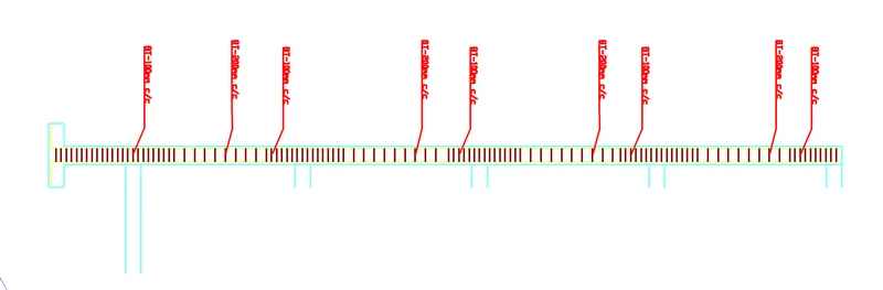
- The shear reinforcement spacing details can be seen clearly in the above diagram, while the plan view of it and the lapping details are shown below.