Drafting of various geometries using Chamfer, Fillet tool in AutoCad
Aim: Drafting of various geometries using Chamfer, Fillet tool in AutoCAD.
Introduction: The various commands used in the following project are introduced over here:
- Circle: To draw Circle
- Line: To draw lines.
- Dimension: For linear, radius, or angular dimensions of the objects.
- Fillets: To make a curvature at a given intersection of two lines at any desired radius.
- Offset: To draw the same object with the same dimensions at a particular distance from the first one.
- Trim and Extend: To trim or extend any particular part of the drawing.
- Snap tool: To take reference of other objects to draw another object.
- Arc: To draw an arc of particular distances and radii.
- Divide: To divide any segment into no. of equal parts as desired.
- Ptstyle: To style the point markings done on the line after dividing it or anything else.
1) Decimal Sheet:
- Drawing 1:
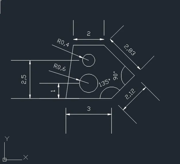
Procedure:
- Start with the command line!
- After drawing the whole boundary with the line, use the command circle.
- Draw two circles of radius 0.4 and 0.6 at given distances from the vertex.
- Give the dimension specifications of the whole figure.
- Drawing 2:
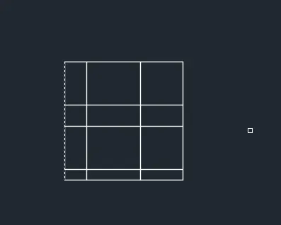
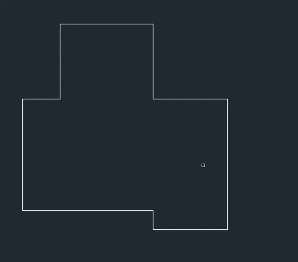
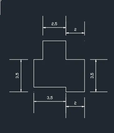
Procedure:
- Start with the command rectangle and draw a square with the length of 5.50 units!
- After drawing the whole boundary with the rectangle, use the command offset.
- Take offsets of all the lengths.
- Then use the trim command to reach the final product.
- Give the dimension specifications of the whole figure.
- Drawing 3:
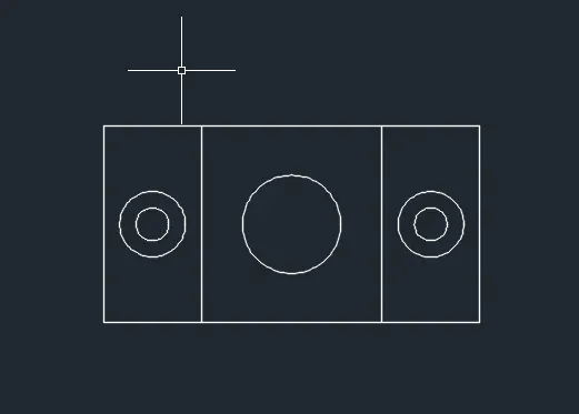
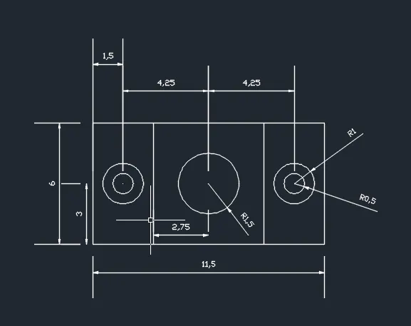
Procedure:
- Start with the command line!
- After drawing the whole boundary with the line, use the command circle.
- Draw two circles of radius 0.5 and 1 at given distances from the vertex on both the sides of the rectangle as shown in the figure.
- Draw a circle in the center part of the figure of radius 1.5 units.
- Give the dimension specifications of the whole figure.
- Drawing 4:
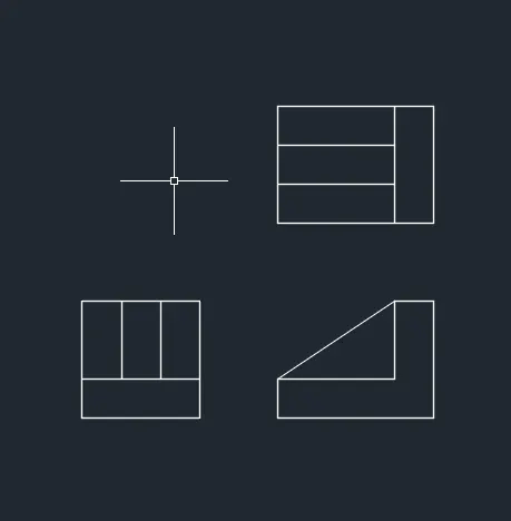
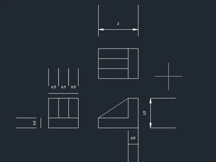
Procedure:
- Start with the command line!
- After drawing the whole boundary with the line.
- Use the offset command for drawing lines at a distance of 0.5 units.
- Give the dimension specifications of the whole figure.
- Drawing 5:
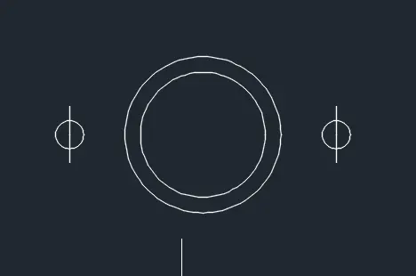
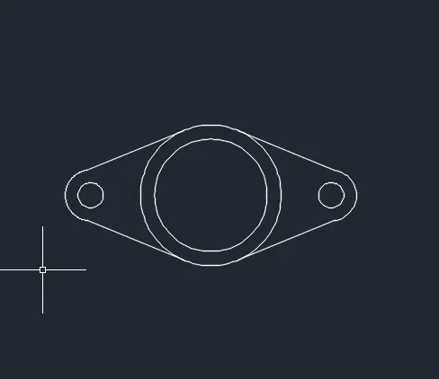
Procedure:
- Start with the command circle.
- Draw two circles at given distances from the vertex and one at the center.
- Draw an arc to both the outer circles of a radius of 0.90 units.
- Draw a tangent from all the open points of the arcs to the bigger circle.
- Give the dimension specifications of the whole figure.
- Drawing 6:
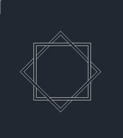
Procedure:
- Start with the command Rectangle and draw 2 squares, one normal and the other at a 45-degree angle from the other.
- Take an offset of both the squares and use the trim command to reach the final sketch.
- Drawing 7:
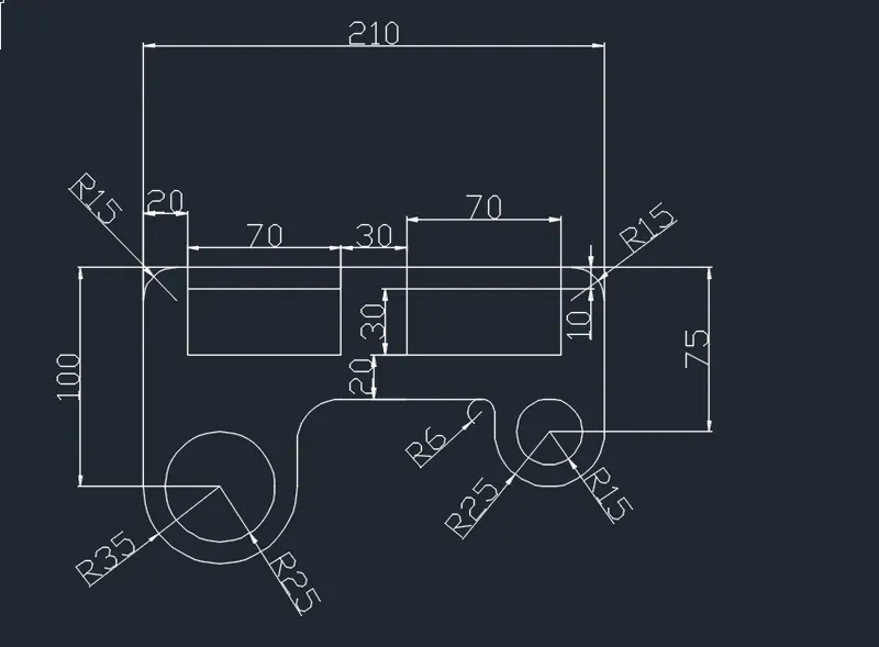
Procedure:
- Start with the command line!
- After drawing the whole boundary with the line, use the command circle.
- Draw two circles of radius 25 and 15 at given distances from the vertex.
- Then draw the arcs of radius 35 and 25 from the center of the circles with radii 25 and 15 respectively.
- Draw twp rectangles of 70 x 30 units at given distances from the vertex.
- Take the fillet command next and apply the fillets of asked radii to the figure at respective points.
- Give the dimension specifications of the whole figure.
2) Engineering Sheet:
- Drawing 8:
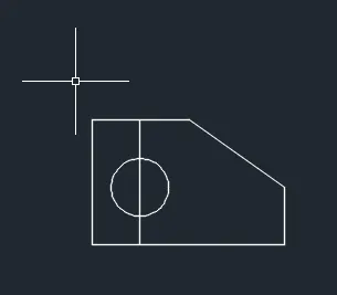
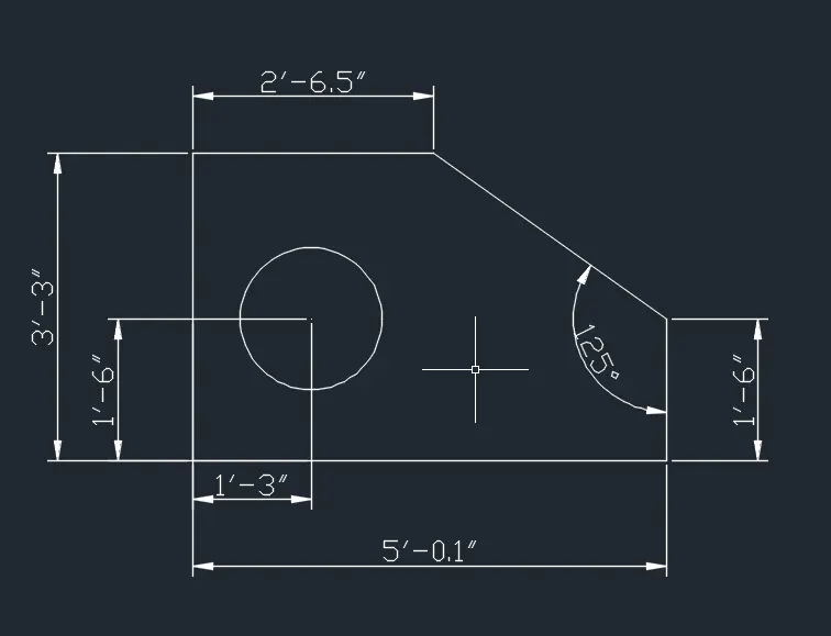
Procedure:
- Start with the command line!
- After drawing the whole boundary with the line, use the command circle.
- Draw a circle at a given distance from the vertex.
- Give the dimension specifications of the whole figure.
- Drawing 9:
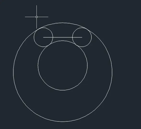
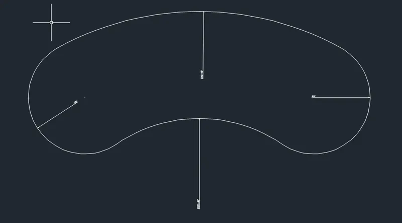
Procedure:
- Start with the command circle.
- Draw two circles of given radii.
- Draw two circles using the three-point method of the circle formation of the given radii to reach the final sketch.
- Give the dimension specifications of the whole figure.
3) Architectural Sheet:
- Drawing 10:
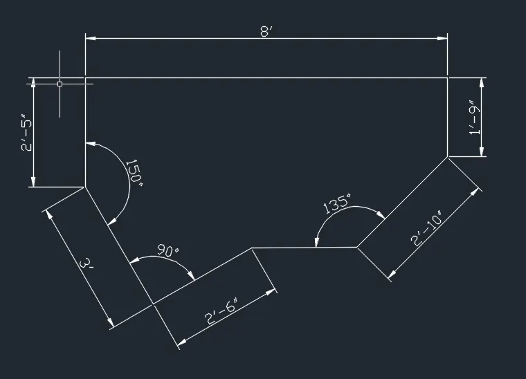
Procedure:
- Start with the command line and draw the whole figure!
- Give the dimension specifications of the whole figure.
- Drawing 11:
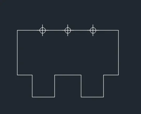
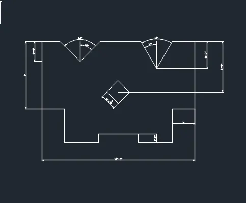
Procedure:
- Start with the command line!
- After drawing the whole boundary with the line, use the command rectangle.
- Draw a square of 3' 0" length at a given distance from the vertex.
- Now divide the top line into four parts and then draw the declinations at the angles of 90 and 60 degrees of depth asked for each respectively.
- Give the dimension specifications of the whole figure.
Results: All the tools mentioned in the introduction are used to create all 11 drawings. The final snip of each drawing is attached in the above procedure, and the dwd file in which all the drawings were drawn originally is attached below in the attachments section, please find it below.