Reinforcement detailing of Columns from ETABS output
Question
Reinforcement detailing of columns in Etabs 2018.
The ETABS file for a G+4 building is provided. Run the analysis and design the RCC Moment Resisting Frame. The following challenge deals specifically with two columns at the following grid intersections.
- 3A
- 3B
- Provide details of longitudinal reinforcement for the two columns, from foundation to terrace level. Sketch the column cross sectional & elevation details or draft it using autocad software.
- Show shear reinforcement & lapping details as per special confining reinforcement provision of clause 8.1 of IS 13920 - 2016.
Ans.
Aim:-
- To provide the detils of longitudenal reinforcement for two column (3A & 3B), from foundation to terrace level.
- To provide the details of shear reinforcement as per special confining reinforcement provision of clause 8.1 of IS 13920 - 2016.
Introduction:-
- A reinforced concrete column is a structure member designed to carry compressive loads, composed of concrte with an embeded steel frame to provide reinforcement.
- For deisgn purpose, the columns are seperated into two categories : short column and slender columnss.
- A short column is a structure member whose relative short length virtualy ensure it will fail in compression if evenly loaded on axis.
- Cloumn can be easily classified as Short, itermediate , long depending upon their length, their material properties, and length of other column in same strcuture.
- A slender column is a thin column, for any construction, foundation starts making the position of columns and then design & anaylsis.
- Slender column can be tested in lab to observe the action of buckling and cripping. For column based on slenderness ratio is termed as long or short column.
Procedure:-
Step 1:
- First we have to open the challenge 7, and download it.
- Open challenge in ETABS
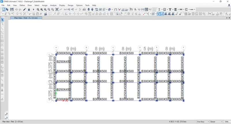
Step 2:
- Now put model in elevation view as shown below
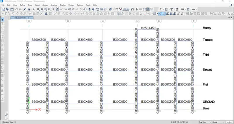
Step 3:
- Start design by selecting Start design/ Check option
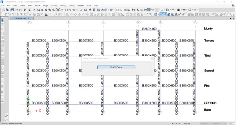
Step 4:
- Design longitudnal reinforcement
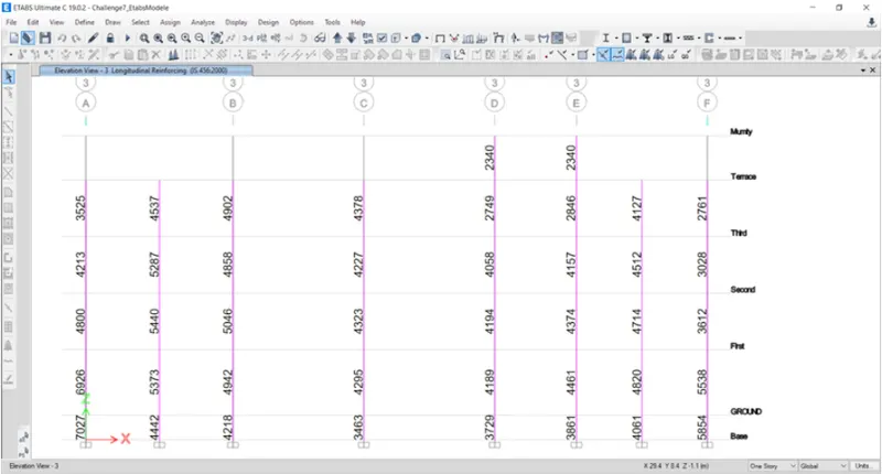
Step 5:
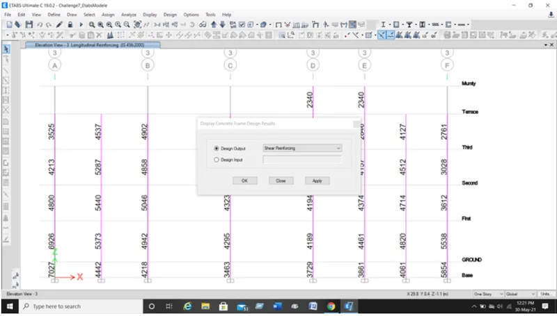
- Select Display Design info, select shear reinforcement design output and then click on OK button
- Shear reinforcement will be displayed as hown below
Step 6:
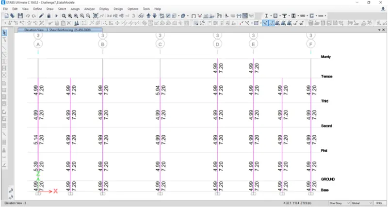
- Shear reinforcement will be dislayed as shown below
Step 7:
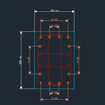
- Now, here column-7 (3A intersection), we take size of column is 450X650 mm.
- Max. Ast for column-7 is 7027sq.m.
- Now we will provide 16bars with18mm dia (16-18ø) as shown below
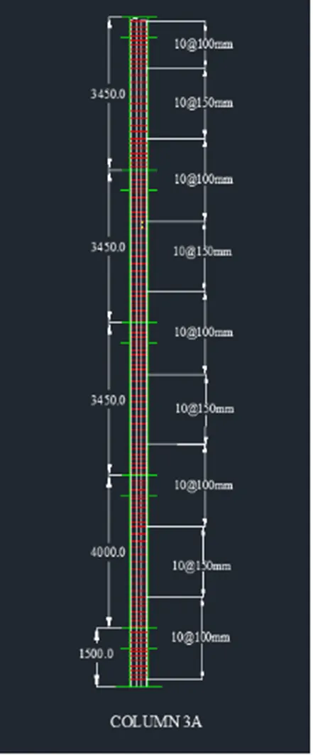
- Provide stirrups as 10mm, for Zone A we provide 100mm spacing and for Zone C provide 150mm spacing, as shown below
- Deatil of shear reinforcement are provided as per special confining reinforcement provision of clause 8.1 of IS 13920-2016.
Step 8:
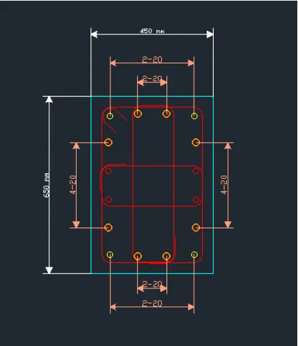
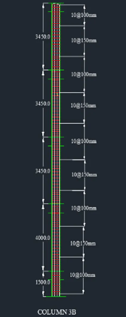
- Here column-8 (3A intersection), we take size of column is 450X650 mm
- Max. Ast for column-8 is 5046sq.m.
- Now we will provide 16bars with 20mm dia (16-20ø) as shown below
- Provide stirrups as 10mm, for Zone A we provide 100mm spacing and for Zone C provide 150mm spacing, as shown below
- Deatil of shear reinforcement are provided as per special confining reinforcement provision of clause 8.1 of IS 13920-2016.
Result :-
- Provided the details od longitudnal reinforcement of two column (3A & 3B) successfully, from foundation to terrace level.
- Provided with deatiling of shear reinforcement as per special confining reinforcement provision of clause 8.1 of IS 13920 - 2016.
- Provided with cross section of column & elevation using AutoCAD software.