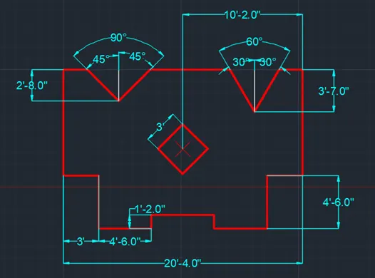
Drafting of various geometries using Chamfer, Fillet tool in AutoCad
Commands used are
- Line
- Circle
- Rectangle
- Trim
- Copy
- Mirror
- Offset
- Polygon
- Point
- Rotate
- Fillet
Que.1.
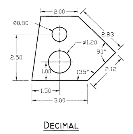
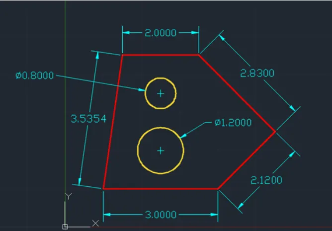
Aim :- To draw the above figure in AutoCAD
Introduction :- Decimal units are unitless — that is, they’re not based on any particular real-world unit. With decimal units, each unit in the drawing could represent an inch, a millimeter, a parsec, a furlong, a fathom, a cubit (if you’re into building arks in case that rainy day should come), or any other unit of measure you deem suitable, from Danish alens to the Swiss zoll. An example would be 15.5.
Open grid and snap settings
- Change snap and grid spacing to 1
- Change major line every grid line to 10
- Turnoff adaptive grid
Procedure :-
Step1 :- Drawing of outer box
Select the Line tool by entering ‘Line’ command in the command tab.
- Specify the first point : Type (1,1) and press enter
- Specify the next point : Type (4,1) and press enter
- Specify the next point : Type @2.12<45 and press enter
- Specify the next point : Type @2.83<135 and press enter
- Specify the next point : Type @(-2,0) and press enter
- Specify the next point (Close:Exit:Undo) : Press close the complete the box
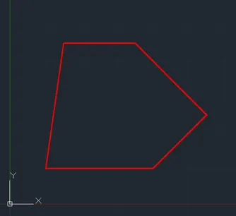
Step2 :- Drawing of bottom inner circle
Type "C" or select circle from draw toolbox
- Specify center point of circle : Type(2.5,2) and press enter
- Specify radius of circle or diameter : Press diameter and type 1.2 and enter OR press radius and type 0.6 and press enter
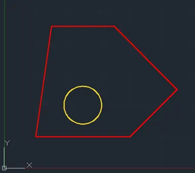
Step3 :- Drawing of top inner circle
Type "C" or select circle from draw toolbox
- Specify center point of circle : Type(2.5,3.5) and press enter
- Specify radius of circle or diameter : Press diameter and type 0.8 and enter OR press radius and type 0.4 and press enter
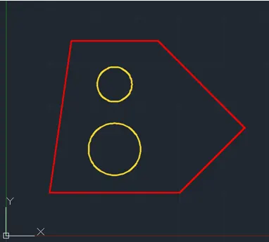
Result :-
- All the dimensions are in meter
- Decimal drawing details in Red and Yellow color
- Dimensions in Cyan
Que.2.
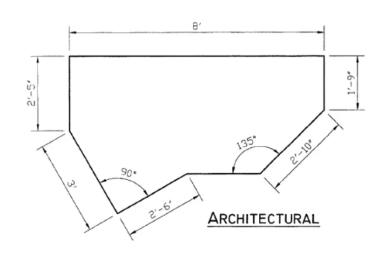
Aim :- To draw the above figure in AutoCAD
Introduction :- Architectural units are based in feet and inches and use fractions to represent partial inches: for example, 12′3 1/2″. The base unit is the inch unless otherwise specified, so if you enter a number like 147.5, then AutoCAD will understand it to be 12′3 1/2″.
Create an imperial drafting sheet
Open grid and snap settings
- Change snap and grid spacing to 1
- Change major line every grid line to 10
- Turnoff adaptive grid
Procedure :-
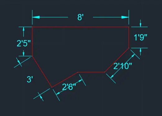
Step1 :- Drawing of right side of figure
Select the Line tool by entering ‘Line’ command in the command tab.
- Specify the first point : Type (1,9) and press enter
- Specify the next point : Type @8',0 and press enter
- Specify the next point : Type @0,-1'9" and press enter
- Specify the next point : Type @2'10" <225 and press enter

Step2 :- Drawing of left side of figure
Select the Line tool by entering ‘Line’ command in the command tab.
- Specify the first point : Turn on ONSNAP and select the top left end point or start point
- Specify the next point : Type @-2'5",0 and press enter
- Specify the next point : Type @3'<300 and press enter
- Specify the next point : Type @2'6" <30 and press enter
- Specify the next point (Close : Exit :Undo) :Turn on ONSNAP and select the end point point drawn in last step
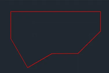
Result :-
- All the dimensions are in Feet and Inchesmeter
- Decimal drawing details in red color
- Dimensions in cyan
Que.3.
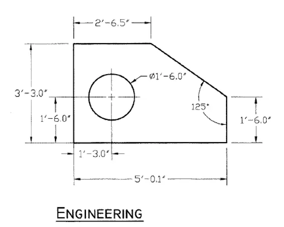
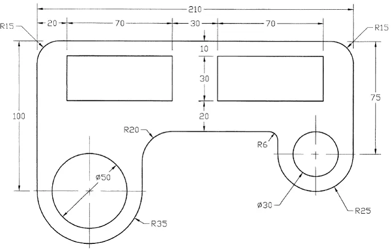
Aim :- To draw the above figure in AutoCAD
Introduction :- Engineering units are based in feet and inches and use decimals to represent partial inches: for example, 12′3.5″.
Create an imperial drafting sheet
Open grid and snap settings
- Change snap and grid spacing to 1
- Change major line every grid line to 10
- Turnoff adaptive grid
Procedure :-
Step1 :- Drawing of outer box
Select the Line tool by entering ‘Line’ command in the command tab.
- Specify the first point : Type (9,5) and press enter
- Specify the next point : Type @0, -1'6" and press enter
- Specify the next point : Type @-5'0.1",0 and press enter
- Specify the next point : Type @0,3'3" and press enter
- Specify the next point : Type @2'6.5",0 and press enter
- Specify the next point (Close:Exit:Undo) : Press close the complete the box
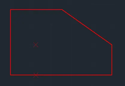
Step2 :- Creating points for inner circle
Type PDMODE and press enter and type 3 and press enter
Type "po" or point in command box and press enter
Turn on Polar tracking
- Keep the cursor on bottom left corner of the box and then move its righr side of that point for polar tracking and type 1'3" and press enter
- Keep the cursor on the last point created and move it up for polar tracking and type 1'6" and press enter
Result :-
- All the dimensions are in Feet and Inches
- Decimal drawing details in Red and Yellow color
- Dimensions in Cyan
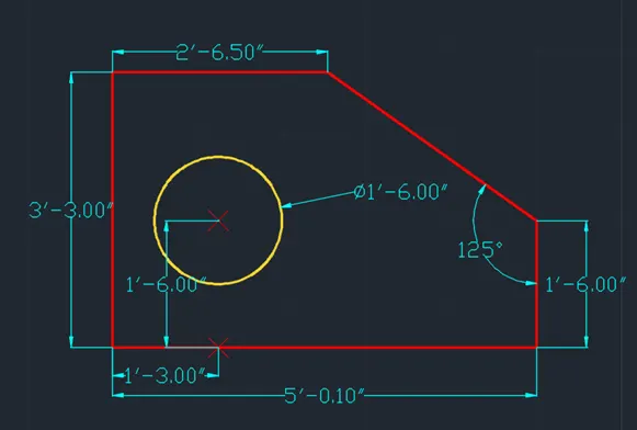
Que.4.
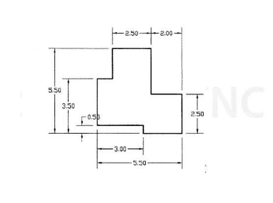
Aim :- To draw the above figure in AutoCAD
Introduction :- Decimal units are unitless — that is, they’re not based on any particular real-world unit. With decimal units, each unit in the drawing could represent an inch, a millimeter, a parsec, a furlong, a fathom, a cubit (if you’re into building arks in case that rainy day should come), or any other unit of measure you deem suitable, from Danish alens to the Swiss zoll. An example would be 15.5.
Create an imperial drafting sheet
Open grid and snap settings
- Change snap and grid spacing to 1
- Change major line every grid line to 10
- Turnoff adaptive grid
Procedure :-
Step1 :- Drawing of outer box
Select the Line tool by entering ‘Line’ command in the command tab.
- Specify the first point : Type (1,1) and press enter
- Specify the next point : Type @3,0 and press enter
- Specify the next point : Type @0,-0.5 and press enter
- Specify the next point : Type @2.5,0 and press enter
- Specify the next point : Type @0,2.5 and press enter
- Specify the next point : Type @-2,0 and press enter
- Specify the next point : Type @0,3 and press enter
- Specify the next point : Type @-2.5,0 and press enter
- Specify the next point : Type @0,-2 and press enter
- Specify the next point : Type @-1,0 and press enter
- Specify the next point (Close:Exit:Undo) : Press close the complete the box
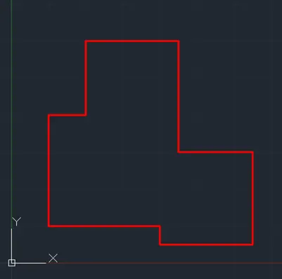
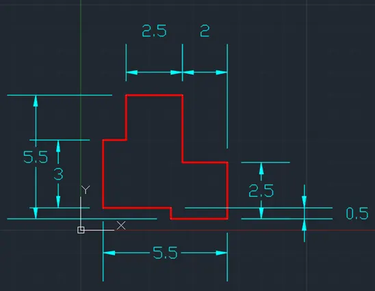
Result :-
- All the dimensions are in meter
- Decimal drawing details in Red
- Dimensions in Cyan
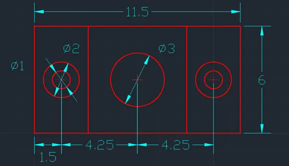
Que.5.
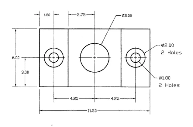
Aim :- To draw the above figure in AutoCAD
Introduction :- Decimal units are unitless — that is, they’re not based on any particular real-world unit. With decimal units, each unit in the drawing could represent an inch, a millimeter, a parsec, a furlong, a fathom, a cubit (if you’re into building arks in case that rainy day should come), or any other unit of measure you deem suitable, from Danish alens to the Swiss zoll. An example would be 15.5.
Create an imperial drafting sheet
Open grid and snap settings
- Change snap and grid spacing to 1
- Change major line every grid line to 10
- Turnoff adaptive grid
Procedure :-
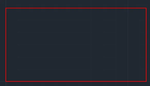
Step1 :- Drawing of Rectangle
Select or type the Rectangle tool by entering ‘rec’ command in the command tab.
- Specify the first corner point : Type (10,10) and press enter
- Specify the other corner point or [Area : Dimension : Rotation]: Click on dimension
- Specify the length for rectangle : Type 11.5 and press enter
Step2 :- Drawing of geometric center on Rectangle and geometric center of left rectangle
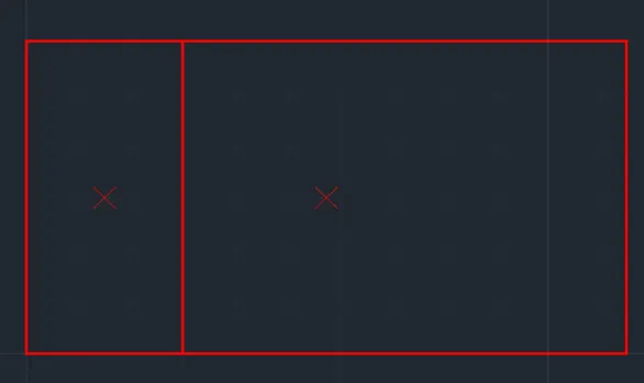
Select the Line tool by entering ‘Line’ command in the command tab.
- Specify the first point : Type (13,10) and press enter
- Specify the next point : Turn on perpendicular in Onsnap and select the perpendicular point on opposite side of rectangle
Type PDMODE and press enter and type 3 and press enter
Type "po" or point in command box and press enter
- Specify a point : Slect the geometric center of rectangle
Type "po" or point in command box and press enter
- Specify a point : Slect the geometric center of rectangle
Step3 :- Drawing of left side holes of figure and center hole
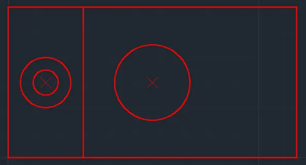
Type "C" or select circle from draw toolbox
- Specify center point of circle : Turn on Onsnap and click on the point as geometric
- Specify radius of circle or diameter : Press diameter and OR press radius and type 3 and press enter
Type "C" or select circle from draw toolbox
- Specify center point of circle : Turn on Onsnap and click on the point as geometric
- Specify radius of circle or diameter : Press diameter and OR press radius and type 1 and press enter
Type "C" or select circle from draw toolbox
- Specify center point of circle : Turn on Onsnap and click on the point as geometric
- Specify radius of circle or diameter : Press diameter and OR press radius and type 2 and press enter
Step4 :- Drawing Or creating mirror image of left rectangle
Type "mi" or mirror in the command box and press enter or select mirror from modify tool bar
- Select objects : select left rectangle, center point created and two circle holes and press enter
- Select first point of mirror line : Select the geometric center of main rectangle
- Select second point of mirror line : turn on orthomode and select any edge along the length
- Erase source object [ Y/N] : Click N i.e no
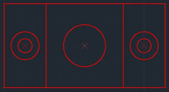
Result :-
- All the dimensions are in meter
- Decimal drawing details in Red
- Dimensions in Cyan
Que.6.
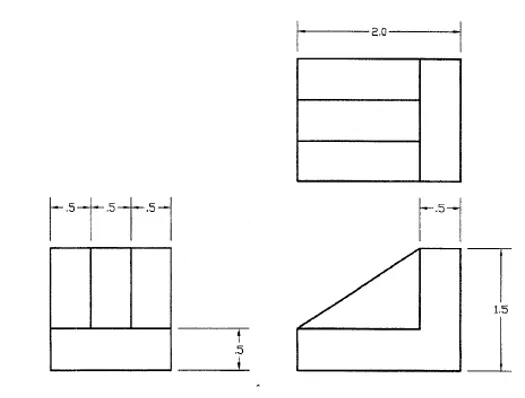
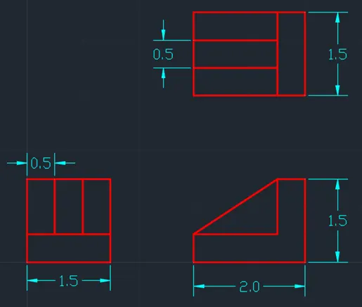
Aim :- To draw the above figure in AutoCAD
Introduction :- The above figure to be drawn throught its different view
- Change snap and grid spacing to 1
- Change major line every grid line to 10
- Turnoff adaptive grid
Procedure :-
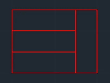
Step1 :- Drawing the Top view of given figure
Select the Rectangle tool by entering ‘rec’ command in the command tab or select rectangle from draw toolbar
- Specify the first corner point: Type (1,1) and press enter
- Specify the other corner point or [Area: Dimension: Rotation] : Click on dimension
- Specify length of rectangle :Type 1.5 and press enter
- Specify width of rectangle :Type 0.5 and press enter and set the direction as first quadrant
Select the Rectangle tool by entering ‘rec’ command in the command tab or select rectangle from draw toolbar
- Specify the first corner point: Turn on Onsnap and select the bottom right corner of the previously drawn rectangle
- Specify the other corner point or [Area: Dimension: Rotation] : Click on dimension
- Specify length of rectangle :Type 0.5 and press enter
- Specify width of rectangle :Type 1.5 and press enter and set the direction as first quadrant
Type "co" or copy command from box or select copy command from the modify tool bar
- Select objects : Select left rectangle drawn previously with dimension 1.5X0.5 and press enter
- Specify base point : Select the bottom right corner of the rectangle selected
- Specify second point: Select the top right of selected rectangle
- Specify second point: Select the top right corner of first copied rectangle to draw another
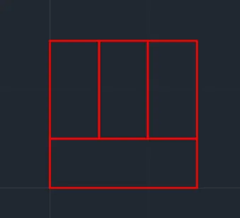
Step 2 :- Drawing the Front view of given figure
Select the Rectangle tool by entering ‘rec’ command in the command tab or select rectangle from draw toolbar
- Specify the first corner point: Type (1,10) and press enter
- Specify the other corner point or [Area: Dimension: Rotation] : Click on dimension
- Specify length of rectangle :Type 2 and press enter
- Specify width of rectangle :Type 0.5 and press enter and set the direction as first quadrant
Select the Rectangle tool by entering ‘rec’ command in the command tab or select rectangle from draw toolbar
- Specify the first corner point: Turn on Onsnap and select the bottom right corner of the previously drawn rectangle specify other corner or [Area: Dimension: Rotation] : Click on dimension
- Specify length of rectangle :Type 0.5 and press enter
- Specify width of rectangle :Type 1 and press enter and set the direction as first quadrant
Select the Line tool by entering ‘LINE’ command in the command tab or draw tool bar
- Specify the first point: Turn on Onsnap and select the top left corner of bottom horizontal rectangle
- Specify the next point: Turn on Onsnap and select the top left corner of top vertical rectangle
Type "tr" or select circle from draw toolbox or select trim from modify tool bar
- Select object : Press enter to select all the objects
- Trim : Select the common line for the both rectangles
- Press ESc to cancel the command
Step 3 :- Drawing the Side view of given figure
Select the Rectangle tool by entering ‘rec’ command in the command tab or select rectangle from draw toolbar
- Specify the first corner point: Type (10,10) and press enter
- Specify the other corner point or [Area: Dimension: Rotation] : Click on dimension
- Specify length of rectangle :Type 1.5 and press enter
- Specify width of rectangle :Type 0.5 and press enter and set the direction as first quadrant
Select the Rectangle tool by entering ‘rec’ command in the command tab or select rectangle from draw toolbar
- Specify the first corner point: Turn on Onsnap and select the bottom right corner of the previously drawn rectangle specify other corner or [Area: Dimension: Rotation] : Click on dimension
- Specify length of rectangle :Type 0.5 and press enter
- Specify width of rectangle :Type 1 and press enter and set the direction as first quadrant
Type "co" or copy command from box or select copy command from the modify tool bar
- Select objects : Select left rectangle drawn previously with dimension 0.5X1 and press enter
- Specify base point : Select the bottom left corner of the rectangle selected
- Specify second point: Select the bottom right corner of selected rectangle
- Specify second point: Select the bottom right corner of first copied rectangle to draw another
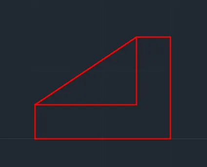
Result :-
- All the dimensions are in meter
- Decimal drawing details in Red
- Dimensions in Cyan
Que.7.
Aim :- To draw the above figure in AutoCAD
Introduction :- The above figure to be drawn as per the given size and with detailing.
Assuming 1 unit as 10 meters
Open grid and snap settings
- Change snap and grid spacing to 1
- Change major line every grid line to 10
- Turnoff adaptive grid
Procedure :-
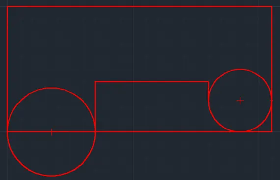
Step1 :- Drawing the Outer component of given figure
Select the Rectangle tool by entering ‘rec’ command in the command tab or select rectangle from draw toolbar
- Specify the first corner point: Type (10,10) and press enter
- Specify the other corner point or [Area: Dimension: Rotation] : Click on dimension
- Specify length of rectangle :Type 21 and press enter
- Specify width of rectangle :Type 10and press enter and set the direction as first quadrant
Type "po" or point command from box and press enter
- Specify a point: Keep the cursor on bottom corner of previous rectangle drawn and start polar tracking to right and type 3.5 and press enter
Type "po" or point command from box and press enter
- Specify a point: Keep the cursor on bottom right corner of previous rectangle drawn and start polar tracking to up and type 3 and press enter
Type "C" or select circle from draw toolbox
- Specify center point of circle : Turn on Onsnap and click on the first point created
- Specify radius of circle or diameter : Press diameter and OR press radius and type 3.5 and press enter
Type "C" or select circle from draw toolbox
- Specify center point of circle : Turn on Onsnap and click on the last point created
- Specify radius of circle or diameter : Press diameter and OR press radius and type 2.5 and press enter
Select the Line tool by entering ‘LINE’ command in the command tab or draw tool bar
- Specify the first point: Type (17, 13) and press enter
- Specify the next point: Type (26, 13) and press enter
Select the Line tool by entering ‘LINE’ command in the command tab or draw tool bar
- Specify the first point: Turn on Onsnap and click first end of line drawn above
- Specify the next point: Turn on Onsnap and click first edge of circle drawn at bootom left edge of main rectangle
Select the Line tool by entering ‘LINE’ command in the command tab or draw tool bar
- Specify the first point: Turn on Onsnap and click first end of line drawn above
- Specify the next point: Turn on Onsnap and click first edge of circle drawn at bootom left edge of main rectangle
Step 2 :- Drawing the Inner component of given figure
Select the Rectangle tool by entering ‘rec’ command in the command tab or select rectangle from draw toolbar
- Specify the first corner point: Type (12,19) and press enter
- Specify the other corner point or [Area: Dimension: Rotation] : Click on dimension
- Specify length of rectangle :Type 7 and press enter
- Specify width of rectangle :Type 3 and press enter and set the direction as first quadrant
Type "PDMODE" and press enter and type 2 and press enter
Turn on Polar tracking
Turn on OSNAP and selct center and geometric center
Type "po" or point command from box and press enter
- Specify a point: Keep the cursor on top right corner of previous rectangle drawn and start polar tracking to up and type 3 and press enter
Type "co" or copy command from box or select copy command from the modify tool bar
- Select objects : Select rectangle drawn previously with dimension 7X3 and press enter
- Specify base point : Select the top left corner of the rectangle selected
- Specify second point: Select the point created at 3units distance
Type "C" or select circle from draw toolbox
- Specify center point of circle : Turn on Onsnap and click on the last point created
- Specify radius of circle or diameter : Press diameter and OR press radius and type 2.5 and press enter
Type "C" or select circle from draw toolbox
- Specify center point of circle : Turn on Onsnap and click on the last point created
- Specify radius of circle or diameter : Press diameter and OR press radius and type 1.5 and press enter
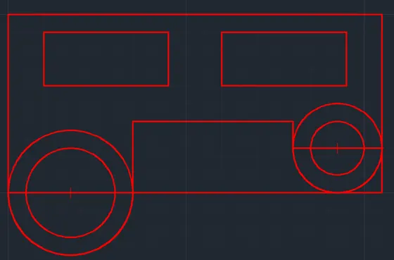
Step 3 :- Drawing or Creating fillet edges of given figure
Type "F" or fillet in command box or selct fillet from the modify tool bar
- Select the first object [Undo : Polyline: Radius :trim :Multiple]: Click on radius
- Specify fillet radius : Type 1.5 and press enter
- Select the first object :Select the left edge of main rectangle
- Select the first object :Select the top edge of main rectangle
Type "F" or fillet in command box or selct fillet from the modify tool bar
- Select the first object [Undo : Polyline: Radius :trim :Multiple]: Click on radius
- Specify fillet radius : Type 1.5 and press enter
- Select the first object :Select the left edge of main rectangle
- Select the first object :Select the top edge of main rectangle
Type "F" or fillet in command box or selct fillet from the modify tool bar
- Select the first object [Undo : Polyline: Radius :trim :Multiple]: Click on radius
- Specify fillet radius : Type 2 and press enter
- Select the first object :Select the left edge of main rectangle
- Select the first object :Select the top edge of main rectangle
Type "F" or fillet in command box or selct fillet from the modify tool bar
- Select the first object [Undo : Polyline: Radius :trim :Multiple]: Click on radius
- Specify fillet radius : Type 0.6 and press enter
- Select the first object :Select the left edge of main rectangle
- Select the first object :Select the top edge of main rectangle
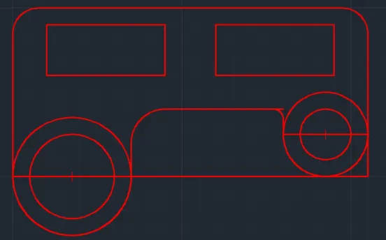
Step 4 :- Drawing trimming needed for given figure
Type "tr" or trim in command box or selct fillet from the modify tool bar
- Select object : Press enter to select all the objects
- Trim: Select the extra portions of outer circle at the bottom of main triangle
- Trim: Select the extra portions of bottom edge of main triangle
- Press Esc or cancel the command or double tap the space bar to stop the command
Erase the remaining object which cannot be trimmed
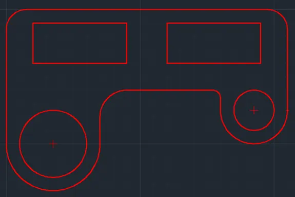
Result :-
- All the dimensions are in meter
- Decimal drawing details in Red
- Dimensions in Cyan
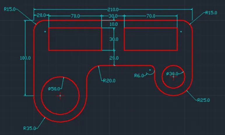
Que.8.
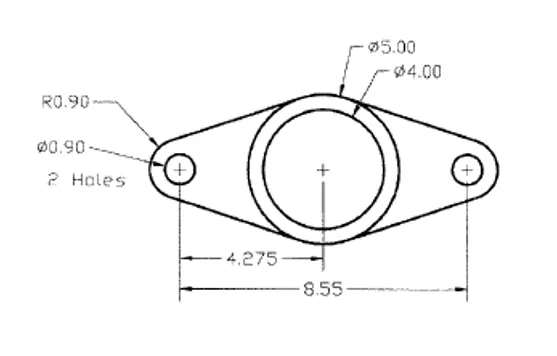
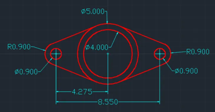
Aim :- To draw the above figure in AutoCAD
Introduction :- The above figure to be drawn as per the given size and with detailing.
Assuming 1 unit as 10 meters
Open grid and snap settings
- Change snap and grid spacing to 1
- Change major line every grid line to 10
- Turnoff adaptive grid
Procedure :-
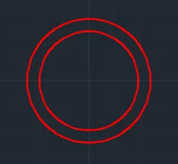
Step1 :- Drawing the Center circles of given figure
Type "C" or select circle from draw toolbox
- Specify center point of circle : Type(10,10) and press enter
- Specify radius of circle or diameter : Press diameter and type 4 and enter OR press radius and type 2 and press enter
Type "C" or select circle from draw toolbox
- Specify center point of circle : Type(10,10) and press enter
- Specify radius of circle or diameter : Press diameter and type 5 and enter OR press radius and type 2.5 and press enter
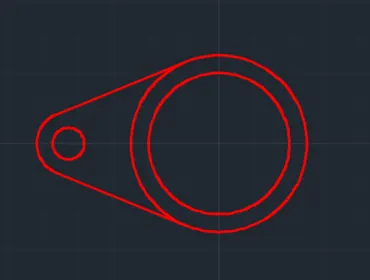
Step 2 :- Drawing the outer two Center circles of given figure
Type "PDMODE" and press enter and type 2 and press enter
Turn on Polar tracking
Turn on OSNAP and selct center and geometric center
Type "po" or point command from box and press enter
- Specify a point: Keep the cursor on top right corner of previous rectangle drawn and start polar tracking to up and type 4.275 and press enter
Type "C" or select circle from draw toolbox
- Specify center point of circle : Select point to be drawn before and press enter
- Specify radius of circle or diameter : Press diameter and type 0.9 and enter OR press radius and type 0.45 and press enter
Type "C" or select circle from draw toolbox
- Specify center point of circle : Select point to be drawn before and press enter
- Specify radius of circle or diameter : Press diameter and type 0.9 and enter OR press radius and type 0.45 and press enter
Type"L" the Line tool by entering ‘LINE’ command in the command tab or draw tool bar
- Specify the first point: Type tan and press enter
- Line to select: Select the outer left side circle drawn at top
- Specify the Next point: Type tan and press enter
- Line to select: Select the outer center circle drawn at top
Type"L" the Line tool by entering ‘LINE’ command in the command tab or draw tool bar
- Specify the first point: Type tan and press enter
- Line to select: Select the outer right side circle drawn at top
- Specify the Next point: Type tan and press enter
- Line to select: Select the outer center circle drawn at top
Type "tr" or trim in command box or selct fillet from the modify tool bar
- Select object : Press enter to select all the objects
- Trim: Select the extra portions of outer circle at left and right side of circles drawn
Step 3 :- Drawing the outer two Center circles of given figure
Drawing Or creating mirror image of left rectangle
Type "mi" or mirror in the command box and press enter or select mirror from modify tool bar
- Select objects : select left circle and two tangents
- Select first point of mirror line : Select the geometric center of main circle
- Select second point of mirror line : turn on orthomode and select center of circle
- Erase source object [ Y/N] : Click N i.e no
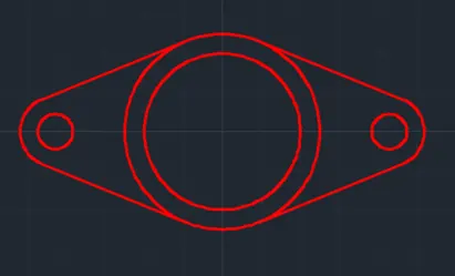
Result :-
- All the dimensions are in meter
- Decimal drawing details in Red
- Dimensions in Cyan
Que.9.
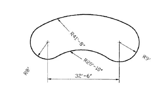
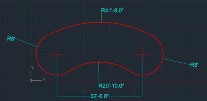
Aim :- To draw the above figure in AutoCAD
Introduction :- The above figure to be drawn as per the given size and with detailing.
Assuming 1 unit as 10 meters
Open grid and snap settings
- Change snap and grid spacing to 1
- Change major line every grid line to 10
- Turnoff adaptive grid
Procedure :-
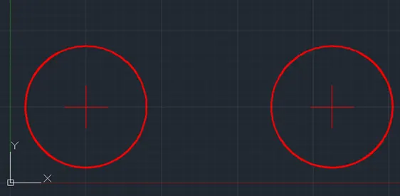
Step1 :- Drawing the two circle of given figure
Type "C" or select circle from draw toolbox
- Specify center point of circle : Type(10,10) and press enter
- Specify radius of circle or diameter : Press diameter and type 8 and enter OR press radius and type 4 and press enter
Type "PDMODE" and press enter and type 2 and press enter
Turn on Polar tracking
Turn on OSNAP and selct center and geometric center
Type "po" or point command from box and press enter
- Specify a point: Keep the cursor on top right corner of previous rectangle drawn and start polar tracking to up and type 32'6" and press enter
Type "po" or point command from box and press enter
- Specify a point : Select the center of circle drawn
Type "co" or copy command from box or select copy command from the modify tool bar
- Select objects : Select previous drawn circle and press enter
- Specify base point : Select the center of circle
- Specify second point: Select the point created at 32'6" distance
Step 2 :- Drawing Tangents to the circle of given figure
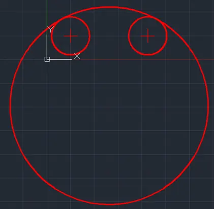
Type "C" or select circle from draw toolbox
- Specify center point of circle : [3P:2P:Ttr (Tan Tan Rad)] : Slect Ttr
- Specify point on object for first tangent of circle :Select at the bottom of circle top point of first circle
- Specify point on object for second tangent of circle :Select at the bottom of circle top point of second circle
- Specify radius of the circle : Type 41'8" and press enter
Step 3 :- Drawing inner circle of given figure
Type "C" or select circle from draw toolbox
- Specify center point of circle : [3P:2P:Ttr (Tan Tan Rad)] : Slect Ttr
- Specify point on object for first tangent of circle :Select at the bottom of circle top point of first circle
- Specify point on object for second tangent of circle :Select at the bottom of circle top point of second circle
- Specify radius of the circle : Type 20'10" and press enter
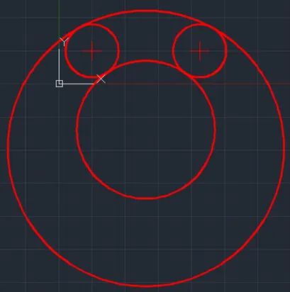
Step 4 :- Drawing trimming needed for given figure
Type "tr" or trim in command box or selct fillet from the modify tool bar
- Select object : Press enter to select all the objects
- Trim: Select the extra portions of outer tangent to circle at the bottom
- Trim: Select the inner portions of main circle as shown below
- Press Esc or cancel the command or double tap the space bar to stop the command
Erase the remaining object which cannot be trimmed
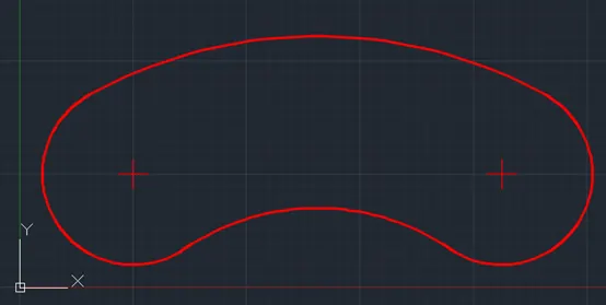
Result :-
- All the dimensions are in Feet and Inches
- Decimal drawing details in Red
- Dimensions in Cyan
Que.10.
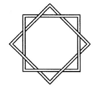
Aim :- To draw the above figure in AutoCAD
Introduction :- The above figure to be drawn as per the given size and with detailing.
Assuming 1 unit as 10 meters
Open grid and snap settings
- Change snap and grid spacing to 1
- Change major line every grid line to 10
- Turnoff adaptive grid
Procedure :-
Step1 :- Drawing the two squares of given figure
Type 'POL' or polygon in command box oe select polygon from thr draw tool bar
- POLYGON enter number of sides : Type 4 and press enter
- Specify center of the polygon : Type 10,10 and press enter
- Enter an option [Inscribed in circle :: Circumscribed in circle] : Click on Inscribed in circle
- Specify radius of circle :Turn on grid and selct at the 5 units in horizontal and vertical direction
Type 'POL' or polygon in command box oe select polygon from thr draw tool bar
- POLYGON enter number of sides : Type 4 and press enter
- Specify center of the polygon : Type 10,10 and press enter
- Enter an option [Inscribed in circle :: Circumscribed in circle] : Click on Inscribed in circle
- Specify radius of circle :Turn on grid and selct at the 7 units in horizontal and vertical direction
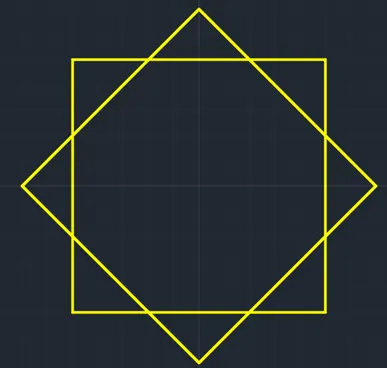
Step 2 :- Drawing the squares offsets on both the sqaure of given figure
Type "O" and press enter or select offset from modify toolbox
- Specify offset distance : Type 0.3 and press enter
- Specify object to offset :Select the straight square and select inside of square to offset
- Specify object to offset :Select the inclined square and select outside of square to offset
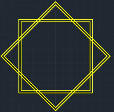
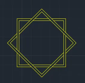
Step 3 :- Trimming the given figure
-
Type "tr" or trim in command box or selct fillet from the modify tool bar
- Select object : Press enter to select all the objects
- Trim: Select the extra portions of sqaure
- Trim: Select the inner portions of square
- Press Esc or cancel the command or double tap the space bar to stop the command
Erase the remaining object which cannot be trimmed (If needed then only do this)
Result :-
- All the dimensions are in mm
- Decimal drawing details in Yellow
Que.11.
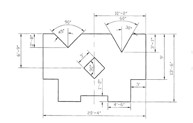
Aim :- To draw the above figure in AutoCAD
Introduction :- The above figure to be drawn as per the given size and with detailing.
Assuming 1 unit as 10 meters
Open grid and snap settings
- Change snap and grid spacing to 1
- Change major line every grid line to 10
- Turnoff adaptive grid
Procedure :-
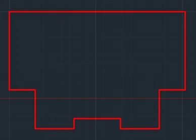
Step 1 :- Drawing the outer box of given figure
Type "L" in command box or select line from draw tool bar
- Specify the start point : Type (10,10) and press enter
- Specify the next point: Type @ (0,-9') and press enter
- Specify the next point: Type @ (3',0) and press enter
- Specify the next point: Type @ (0, -4'6") and press enter
- Specify the next point: Type @ (4'6",0) and press enter
- Specify the next point: Type @ (0, 1'2") and press enter
- Specify the next point: Type @ (5'4",0) and press enter
- Specify the next point: Type @ (0, -1'2") and press enter
- Specify the next point: Type @ (4'6",0) and press enter
- Specify the next point: Type @ (0, 4'6") and press enter
- Specify the next point: Type @ (3',0) and press enter
- Specify the next point: Type @ (0,9') and press enter
- Specify next point (Close:Exit:Undo) :Press close to complete the box
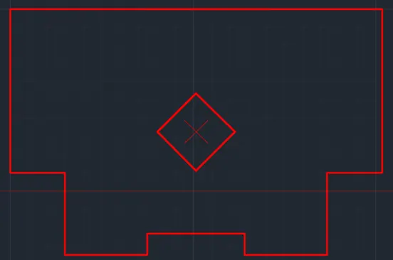
Step 2 :- Drawing the inner polygon of given figure
Type "PDMODE" and press enter and type 3 and press enter
Turn on Polar tracking
Turn on OSNAP and selct center and geometric center
Type "po" or point command from box and press enter
- Specify a point: Turn on the ONSNAP and keep the cursor on the midpoint of top edgr and start polar tracking to down and type 6'9" and press enter
Type "POL" or polygon in command from box or select polygon from drraw tool box press enter
- POLYGON Enter number of sides :Type 4 and press enter
- Specify the center of polygon : Select the point created before
- Enter an option [Inscribed in circle :: Circumscribed in circle] : Click on Inscribed in circle
- Specify radius of circle :selct at the 3 units and press enter
Step 3 :- Drawing the V-section of given figure
Type "PDMODE" and press enter and type 3 and press enter
Turn on Polar tracking
Turn on OSNAP and selct center and geometric center
Type "po" or point command from box and press enter
- Specify a point: Turn on the ONSNAP and keep the cursor on the midpoint of top edgr and start polar tracking to down and type 2'8" and press enter
Type "po" or point command from box and press enter
- Specify a point: Turn on the ONSNAP and keep the cursor on the midpoint of top edgr and start polar tracking to down and type 3'7" and press enter
Type"L" the Line tool by entering ‘LINE’ command in the command tab or draw tool bar
- Specify the first point: Turn on the ONSNAP and ORTHOMODE and select the point created on left side
- Specify the Next point: Turn on ORTHOMODE and draw a line to right of certain distance
Type"L" the Line tool by entering ‘LINE’ command in the command tab or draw tool bar
- Specify the first point: Turn on the ONSNAP and ORTHOMODE and select the point created on left side
- Specify the Next point: Turn on ORTHOMODE and draw a line to left of certain distance
Type"L" the Line tool by entering ‘LINE’ command in the command tab or draw tool bar
- Specify the first point: Turn on the ONSNAP and ORTHOMODE and sele`degree`ct the point created on left side
- Specify the Next point: Turn on ORTHOMODE and draw a line to right of certain distance with angle of 45°
Type"L" the Line tool by entering ‘LINE’ command in the command tab or draw tool bar
- Specify the first point: Turn on the ONSNAP and ORTHOMODE and sele`degree`ct the point created on left side
- Specify the Next point: Turn on ORTHOMODE and draw a line to right of certain distance with angle of 135°
Type"L" the Line tool by entering ‘LINE’ command in the command tab or draw tool bar
- Specify the first point: Turn on the ONSNAP and ORTHOMODE and sele`degree`ct the point created on left side
- Specify the Next point: Turn on ORTHOMODE and draw a line to right of certain distance with angle of 60°
Type"L" the Line tool by entering ‘LINE’ command in the command tab or draw tool bar
- Specify the first point: Turn on the ONSNAP and ORTHOMODE and sele`degree`ct the point created on left side
- Specify the Next point: Turn on ORTHOMODE and draw a line to right of certain distance with angle of 120°
Type "tr" or trim in command box or selct fillet from the modify tool bar
- Select object : Press enter to select all the objects
- Trim: Select the extra portions of sqaure
- Trim: Select the inner portions of square
- Press Esc or cancel the command or double tap the space bar to stop the command
Erase the remaining object which cannot be trimmed (If needed then only do this)
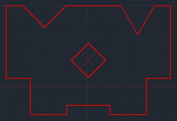
Result :-
- All the dimensions are in Feet and Inches
- Decimal drawing details in Red
- Dimensions in Cyan