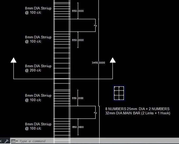
Reinforcement detailing of Columns from ETABS output
OBJECTIVE :
To know the design of RC column using ETABS analysis
To know the basic of RC column reinforcement detailing w.r.t primary standard
To ensure the ductility reinforcement required by IS 13920- 2016 been satisfied in reinforcement drawing
AIM :
To detail reinforcement of columns in Etabs 2018.
To provide details of longitudinal reinforcement for the two columns.
To find shear reinforcement & lapping details as per special confining reinforcement provision of clause 8.1 of IS 13920 - 2016
QUESTIONS :
Reinforcement detailing of columns in Etabs 2018.
The ETABS file for a G+4 building is provided. Run the analysis and design the RCC Moment Resisting Frame. The following challenge deals specifically with two columns at the following grid intersections.
- 3A
- 3B
- Provide details of longitudinal reinforcement for the two columns, from foundation to terrace level. Sketch the column cross sectional & elevation details or draft it using Autocad software.
- Show shear reinforcement & lapping details as per special confining reinforcement provision of clause 8.1 of IS 13920 - 2016.
ANSWERS :
Detailing rule of any RC member,
- Minimum reinforcement for shrinkage & temperature
- Ultimate limit state design rebar requirement
- Ductility rebar requirement
Minimum longitudinal reinforcement as per IS 456- 2000 clause 26.5.3.1
As = 2340mm2
Minimum shear (or) transverse reinforcement as IS 13920- 2016 clause 7.4.2
8mm diameter at 300mm spacing
Development length as per IS 456- 2000 clause 26.2.1
Ld = 41 * diameter of bar
PROCEDURE :
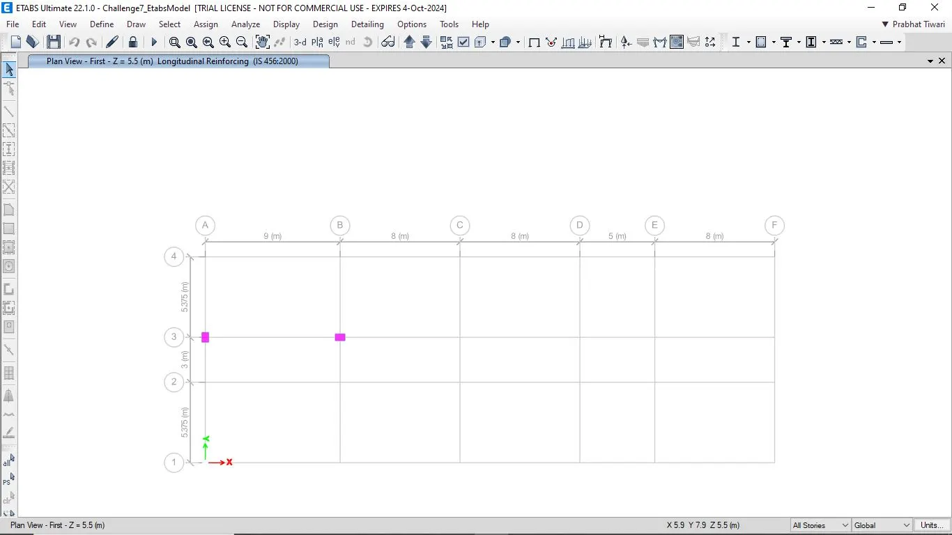
- First open the file in ETABS
- Now in plan section first floor select all stories
- Select the columns from grid 3A and 3B
- Right click on the mouse and select show only selected item
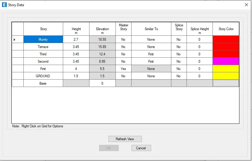
- Now open the elevation plan of grid 3
- Now click on concrete frame design
- Longitudinal reinforcement design area value appear on the column
- Click concrete frame design> Display design info
- Select Shear reinforcement options for lateral ties of column
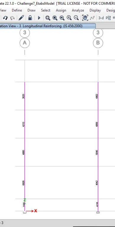
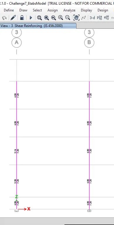
Now Reinforcement Detailing of column 3A
1. Longitudinal Reinforcement
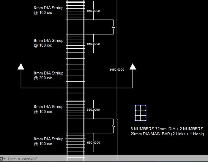
As obtained from the ETABS output, the maximum Ast required is at the base of column and the value for the same is of 6926mm^2. Hence, if we provide 8 bars of 32mm dia and 2 bars of 20mm dia.
Ast = 8x804 + 2x314 = 7060 > 6926 . Hence OK.
2. Shear Reinforcement
Provide 8mm dia Lateral Ties.
3. Confinement Arrangement
Length of the confinement region (L0) = (i) Larger lateral dimensions of the member where yielding occurs
(ii) 1/6th of the clear column span
(iii) 450 mm, whichever is greater
So, in our case, we have the total beam depth of 650mm. Therefore, we shall consider the confinement region up to the 650 mm from beam bottom towards the mid span on either side of the column.
Shear Spacing within the confinement region = (i) 1/4th of the Smaller lateral dimension of column
(ii) 6 X db
(iii) 100mm, whichever is lesser
So, 100mm is the least value we got among all three above values. Therefore, provide 100mm c/c spacing within the confinement zone and go with 200mm c/c for the mid zone of the column.
Thus, using the above values the following detailed drawing was prepared in AutoCAD for the column height.
Now Reinforcement Detailing of column 3B
As obtained from the ETABS output, the maximum Ast required is at the base of column and the value for the same is of 6926mm^2. Hence, if we provide 8 bars of 25mm dia and 2 bars of 32mm dia.
Ast = 2x804 + 8x491 = 5533 > 5046 . Hence OK.
2. Shear Reinforcement
Provide 8mm dia Lateral Ties.
3. Confinement Arrangement
Length of the confinement region (L0) = (i) Larger lateral dimensions of the member where yielding occurs
(ii) 1/6th of the clear column span
(iii) 450 mm, whichever is greater
So, in our case, we have the total beam depth of 650mm. Therefore, we shall consider the confinement region up to the 650 mm from beam bottom towards the mid span on either side of the column.
Shear Spacing within the confinement region = (i) 1/4th of the Smaller lateral dimension of column
(ii) 6 X db
(iii) 100mm, whichever is lesser
So, 100mm is the least value we got among all three above values. Therefore, provide 100mm c/c spacing within the confinement zone and go with 200mm c/c for the mid zone of the column.
Thus, using the above values the following detailed drawing was prepared in AutoCAD for the column height .