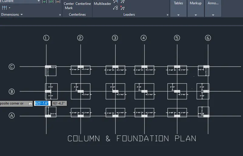
Project 1 _Creating an Architectural plan for the provided plot size and develop relevant basic structural drawings
Aim :
1. Design and Draft a layout of a residential building
2. Architectural Drawing (Floor Plan, Elevations, and Sections)
3. Structural Drawing (Column, Bean, Footing Plan)
Introduction :
Vastu Shastra -
Existence of roads on the northern or eastern side of the house improves the health and progress of the members of the house. If a house has road on the 3 sides, its inhabitants suffer tension and tension related problems. When the digging is happening to lay the foundation, make sure that you start from the east, go to the north, then to the west, and lastly, southwest. The plot at the end of a road is also not good for its inhabitants. It is good to have main door on east, northern and north eastern corner of the house. A house having main door at the southwest end provides less peace and perpetually tense atmosphere. A house having massive main door gives a lot of unsavory events and members residing suffer health problems. There should be no doors in the southwest corners or the southwest portion of the house. It is best if the doors face north or east. Doors should also open inside and not outside. When the door opens inside, it stands for inviting popular powers and positive energy. However, the door opening outside would be bad for the positive energy- it would actually drive the good energy away.
Layouts in AutoCAD -
A layout in AutoCAD represents a 2d space where the user can determine the size of the drawing board and edit the title block and view multiple scenes of the object at the same time.
Plan, Section, and Elevation are different types of drawings used by architects to graphically represent a building design and construction. A plan drawing is a drawing on a horizontal plane showing a view from above. An Elevation drawing is drawn on a vertical plane showing a vertical depiction. A section drawing is also a vertical depiction, but one that cuts through space to show what lies within.
Procedure :
1. Step by Step procedure to create the Plan and Sections of 1st, 2nd, 3rd Floor plan
- Open a new file: Control +N
- Click on Start from scratch & select imperial (metric)
- Enter Drawing unit(UN): UN [Enter]
- Enter LIMMAX(LIM) command: LIM [Enter]
- Put the value of the plot according to our drawing (15000,15000) [Enter]
- Enter ZOOM(Z) command: Z [Enter]
- Enter ALL(A) command: A [Enter] in the ZOOM command
- Another command is LIMITS
- Enter RECTANGLE(REC) command: REC [Enter]
- Enter (fn + f10) : Polar Tracking On
- Enter (fn + f3) : Object Snap On
- Enter (fn + f8) : Ortho On
- Enter (O) : Offset Command
- Enter (DIML) : Dimension Liner Command
- Enter (DIMC) : Dimension Continous Command
- Enter (MT) : Multi Text Command
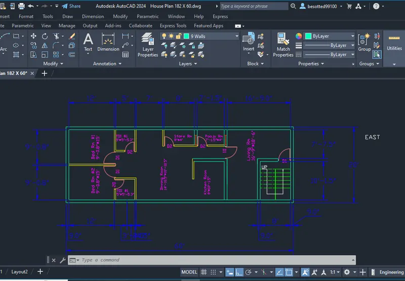
- Complete the Plan and Sections of 1st, 2nd, 3rd Floor as shown in the figure
Result :
1. A layout of a residential building
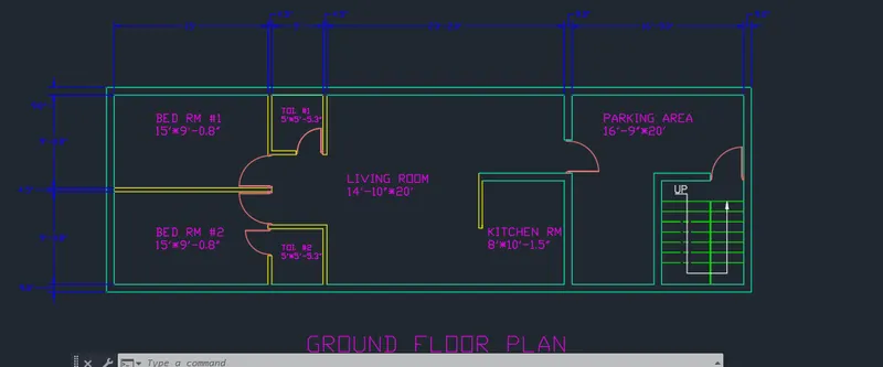
2. Architectural Drawing (Floor Plan, Elevations, and Sections)
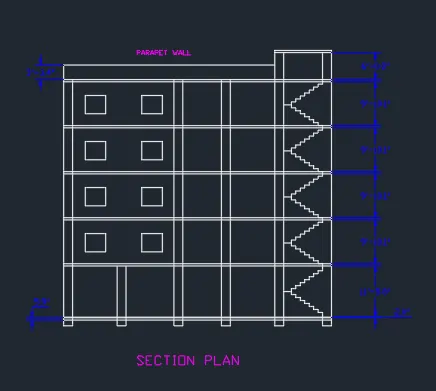
3. Structural Drawing (Column, Bean, Footing Plan)