Reinforcement detailing of Columns from ETABS output
Challange 8:Reinforcement detailing of Columns from ETABS output
Reinforcement detailing of columns in Etabs 2016.
The ETABS file for a G+4 building is provided. Run the analysis and design the RCC Moment Resisting Frame. The following challenge deals specifically with two columns at the following grid intersections.
- 3A
- 3B
AIM:Providing Reinforcement detailing of columns in Etabs 2016.
Procedure:
The G+4 Building is already provided in the previous challange that is 7 so take the same file in etab 2016.
1.Provide details of longitudinal reinforcement for the two columns, from foundation to terrace level. Sketch the column cross sectional & elevation details or draft it using autocad software.
Following Procedure is as follows
Step-1:
- Open the file and unlock it
- Check the loads acting on it in the load pattern.
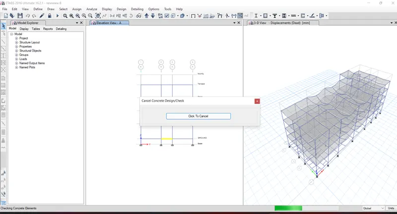
- Further analyse the model to check is there any errors,
- If no errors found then just select Concrete frame design option
- As shown below,
Step-2:
- Select the option as Elevation and select 3A and 3B Elevation.
- And Press left button of mouse and select show only selected beam
- hence it is easy to see.
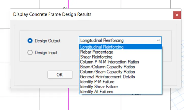
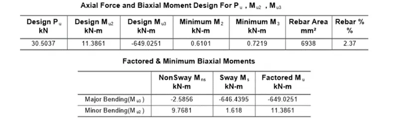
- Now select the longitudinal reinforcement and design the required amount of rebars.


Step-3:
- By observing the given data of longitudinal reinforcement.
- Provide as possible no of reinforcement required.
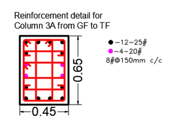
- In 3A the Column size was 450mmx650mm
- Hence it required 6939mm2 reinforcement hence provide 12no. of 25 dia bars and 4no. of 20mm dia bars as shown.
- The above detail is from GF to Third floor
- There after the rebars changes to 8no. of 20mm dia and 8no. of 16mm dia bars upto the terrace as shown below.

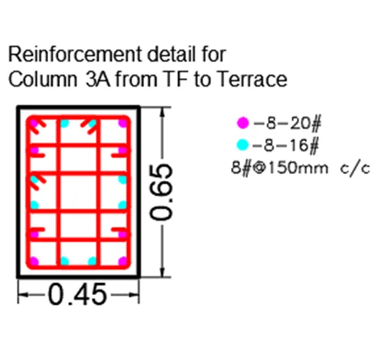
Step-3:
- In 3B the Column size was 450mmx650mm
- Hence it required 4918mm2 reinforcement hence provide 16no. of 20 dia bars as shown.
- The above detail is from GF to Third floor
- There after the rebars changes to 16no. of 16mm dia upto the terrace as shown below.
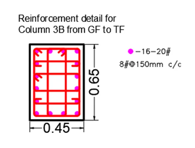
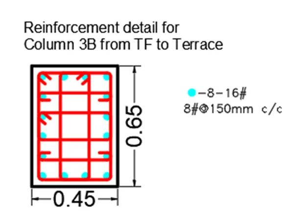
2-Show shear reinforcement & lapping details as per special confining reinforcement provision of clause 8.1 of IS 13920 - 2016.
For Shear Reinforcement just change the option as show shear reinforcement then it shows as shown below
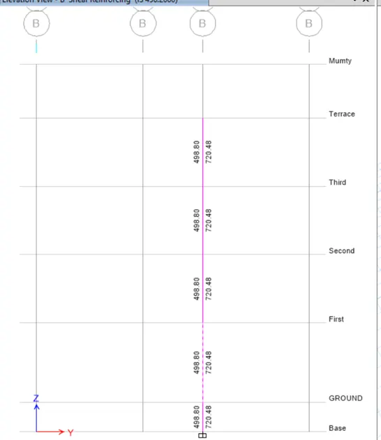
- Hence there is a excel sheet is created wich calculate the no. of Shear reinforcement required
- in which is calculated by formula Ast provided=(1000*no. of legs*ast of stirrup)/Spacing of Stirrup
- Any how in the sismic design evers bar is connected with stirrups and hooks as shown below,
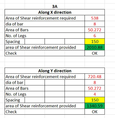
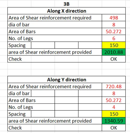
Hence stirrups are provide as 6 legs in the x direction and 4 legs stirrup in the Y @ 150mm c/c as shown Below,
Lapping details as per special confining reinforcement provision of clause 8.1 of IS 13920 - 2016.
Solution,
8.1 Flexural yielding is likely in beams during strong earthquake shaking and in columns when the shaking intensity exceeds the expected intensity of earthquake shaking This special confining reinforcement shall,
- be provided over a length 1, from the face of the joint towards mid-span of beams and mid heights of columns, on either side of the joint; where /is not less than
- larger lateral dimension of the member at the section where yielding occurs,
- 1/6 of clear span of the member
- 450 mm.
- have a spacing not more than,
1) 1/4 of minimum member dimension of the in beam or column
2) 6 times diameter of the smallest the longitudinal reinforcement bars; and
3)100 mm link.
--------------------------------------------------END---------------------------------------------------------