Reinforcement detailing of Columns from ETABS output
Reinforcement detailing of columns in Etabs 2018.
The ETABS file for a G+4 building is provided. Run the analysis and design the RCC Moment Resisting Frame. The following challenge deals specifically with two columns at the following grid intersections.
- 3A
- 3B
- Provide details of longitudinal reinforcement for the two columns, from foundation to terrace level. Sketch the column cross sectional & elevation details or draft it using AutoCAD software.
- Show shear reinforcement & lapping details as per special confining reinforcement provision of clause 8.1 of IS 13920 - 2016.
AIM:
In the given Etabs project we have to analyze and redesign the RCC moment resisting frame in two columns at the following grid intersection 3A & 3B from foundation to terrace level by using etabs with reference of IS 13920-2016
INTRODUCTION:
In the modal we provide the details of longitudinal reinforcement of two columns and shown shear reinforcement, lapping details as per special confining zone of clause 8.1 of IS 1920-21016
PROCEDURE: -
- Open the challenge 7 attachment which are provided to us
- After downloading open the Challenge open it in the Etabs 20 software
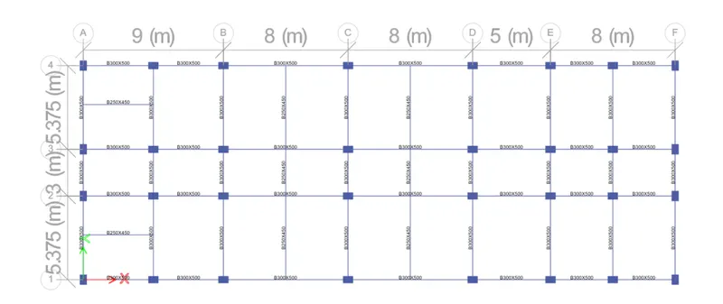
- Select the 3A and 3B columns from all stories as shown a in below;
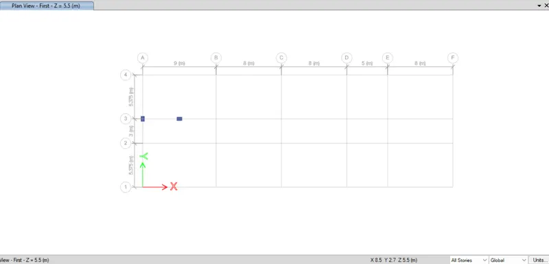
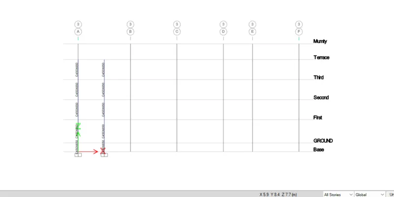
- Change the view into Elevation view - 3
- And Run the Analysis
- Now we have to start the column design by selecting the "concrete frame design" a below showing;
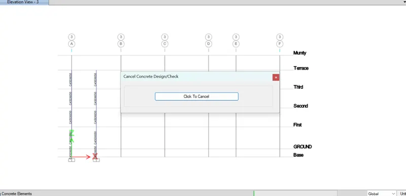
- Below showing longitudinal reinforcement of the columns 3A and 3B after run the analysis
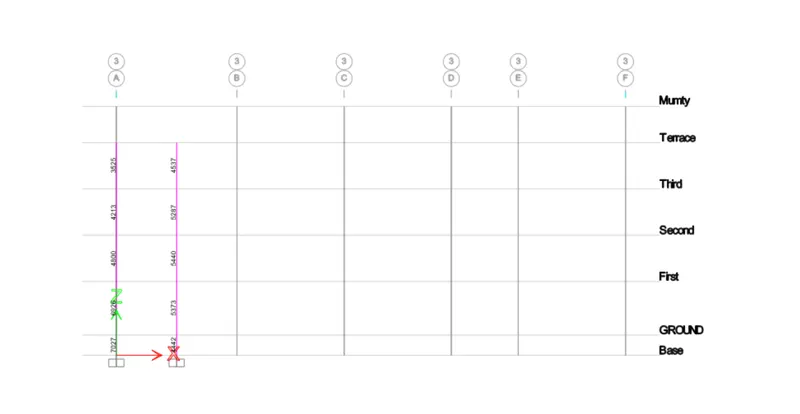
- Now we are separately showing longitudinal reinforcement and shear reinforcement of the columns
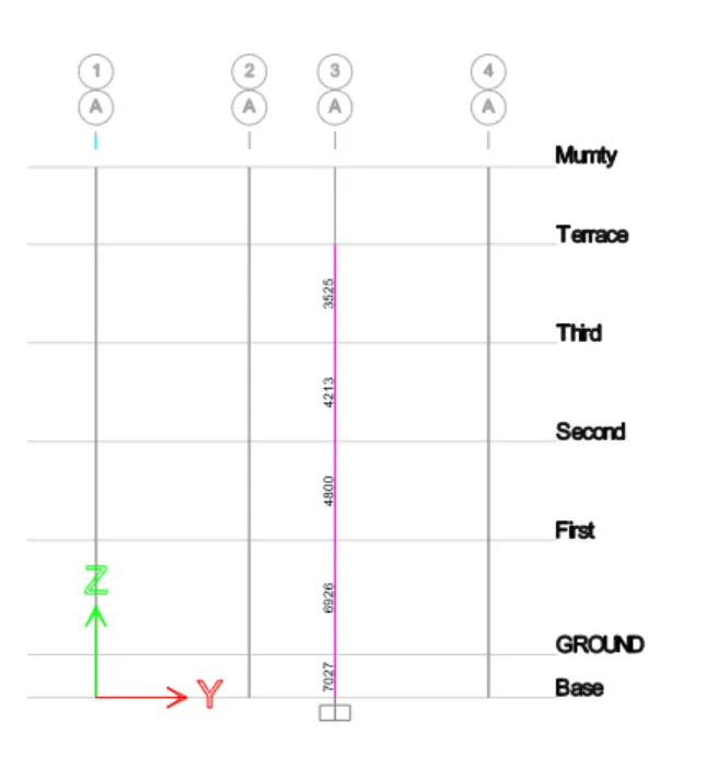
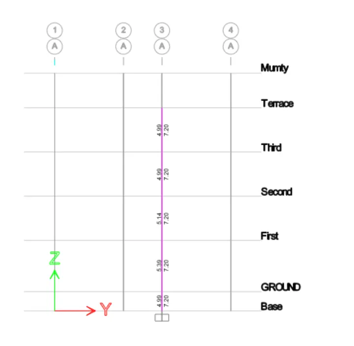
Longitudinal reinforcement and shear reinforcement and Diagrammatical details of the column at grid 3A from ETABS;
1. Longitudinal reinforcement: -
2. Shear reinforcement: -
NOW WE HAVE TO PROVIDE DEATIL REINFORCEMENT TO THE COLUMN;
1. For GRID 3A -
From Base to first floor the maximum Ast = 7027 mm2
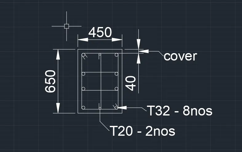
So, we can provide 8 no's of 32 mm diameter bar = 8 x 803.84
= 6430.72 mm2
also, we can provide 2 no's of 20 mm diameter bar = 2 * 314
= 628 mm2
8 no's of 32 mm+2 no's of 20 mm = 6430.72+628
=7058.72 mm2>7027 mm2 ........hence okay
Special confining reinforcement from IS-13920-2016(Clause 8.1)
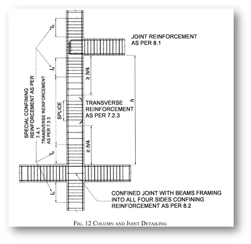
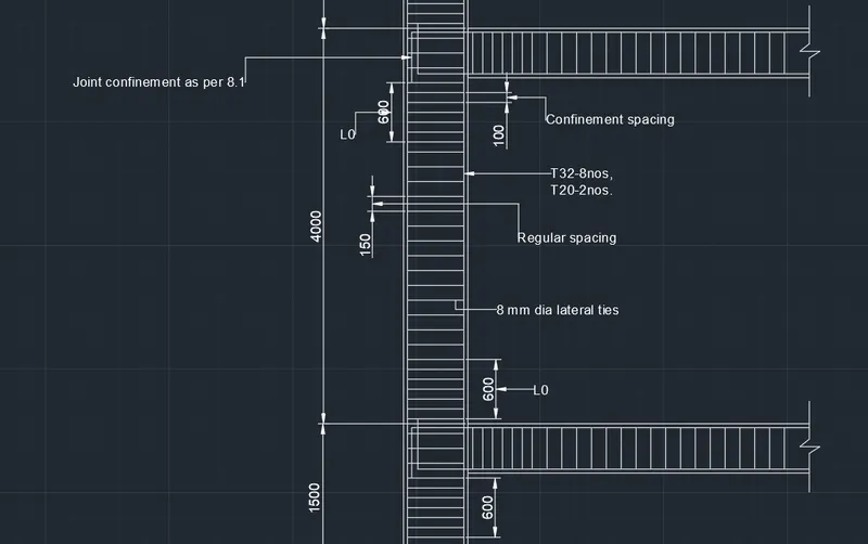
Lo not less than-
- Larger column dimension
- 1/6 of clear span of column
- 450 mm
Confinement spacing not more than-
- ¼ of smaller column dimension
- 6 times of dia of column main bar
- 100mm
The amount of confinement rebar- .
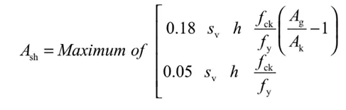
Ash=169mm2
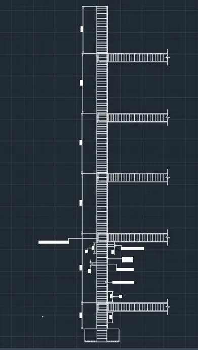
Diagrammatical Details of column at grid 3A are shown below -
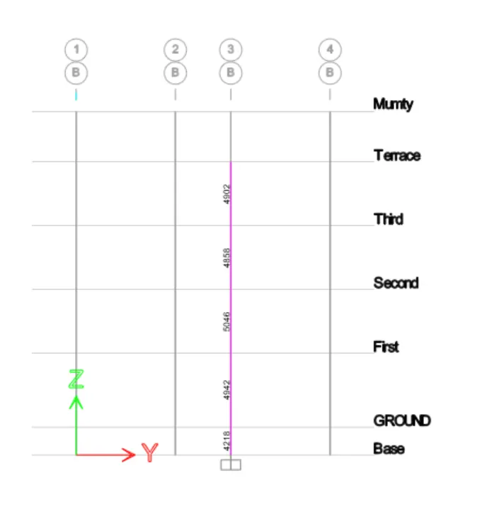
Longitudinal reinforcement and shear reinforcement and Diagrammatical details of the column at grid 3B from ETABS;
1. Longitudinal reinforcement: -
2. Shear reinforcement: -
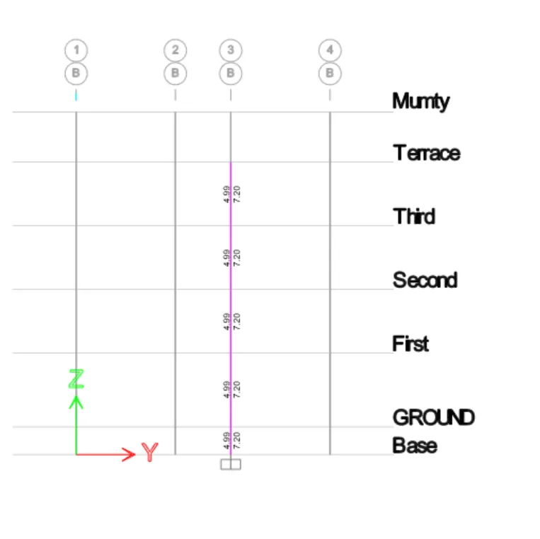
2) For GRID 3B -
From Base to Terrace floor the maximum Ast = 5046 mm2
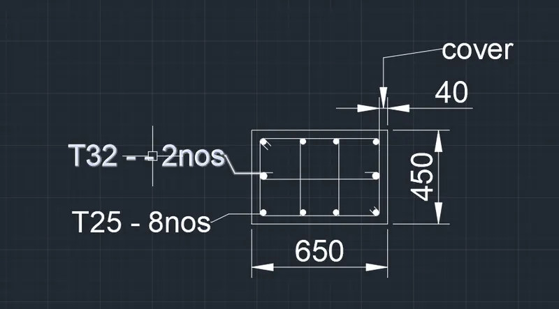
So, Provide 8 bars of 25 mm diameter for the column = 8 x 490.87*8
= 3927mm2
Provide 2 bars of 32 mm diameter for the column = 4 x 314.16
= 1607.68mm2
Therefore;
Provide 8 bars of 25 mm diameter for the column + Provide 4 bars of 20 mm diameter for the column =
= 3927 + 1607.68
= 5534 mm2>5046 ...........hence okay
Special confining reinforcement from IS-13920-2016(Clause 8.1)
Lo not less than-
- Larger column dimension
- 1/6 of clear span of column
- 450 mm
Confinement spacing not more than-
- ¼ of smaller column dimension
- 6 times of dia of column main bar
- 100mm
The amount of confinement rebar- .
Ash=169mm2
Diagrammatical Details of 3B Grid are shown below;
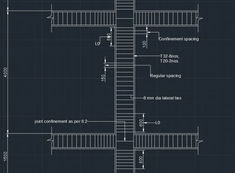
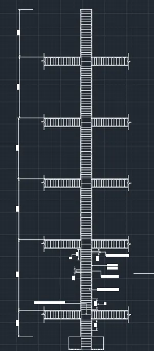
Now, Typical Beam column Joint as per special confining reinforcement provision of clause 8.1 of IS 13920 -2016
As per IS 13920 - 2016 at beam column junction: -
- For beam - The spacing from the face of the beam should not be more than 100 mm till 2d
- For Column - The spacing from the face of the column will be lo and should not be more than least lateral dimension, (16)th of clear span or 450 mm
RESULT: -
- The given Etabs model has been analyzed after checking the model.
- Then concrete frame design has also been carried out hence the reinforcement area required has been obtained.
- The longitudinal reinforcement details obtained from the results have been drafted in AutoCAD software.
- Similarly, the shear reinforcement details also have been drafted.