Creation of geometries by Coordinate system methods using AutoCad
Create the geometries from P1 to P2 using all the coordinates system methods. You need to use the Line tool to create the geometries. Where required you need to use the circle tool.
Please read the drawings and find out the missing dimensions before working on the sketches.
Note: Use the Imperial Template and the Decimal Units to draft the features. Dimensions are there for
references.
Civil Related Problems
Draw the profile and the trusses using any coordinate system methods. The dimensions are there for references.
AIM: To Create the geometries from P1 to P2 using all the coordinates system methods. You need to use the Line tool to create the geometries. Where required you need to use the circle tool.
Introduction:
Coordinate system: There are two coordinate systems in AutoCAD. World Coordinate System (WCS) and User Coordinate System (UCS) which define the angle of the XY plane you are working in. The WCS should always be used to reference geometry to ensure everything aligns to the centre of a file in real-world location.
Absolute coordinate system: Absolute Coordinates is a command for AutoCAD software that uses the Cartesian coordinate system to specify a position in the X, Y, and (if needed) Z axes to locate a point from the 0-X, 0-Y, and 0-Z (0,0,0) point.
Relative coordinate system: Use relative coordinates when you know the location of a point in relation to the previous point. To specify relative coordinates, precede the coordinate values with an @ sign. For example, entering @3,4 specifies a point 3 units along the X axis and 4 units along the Y axis from the last point specified.
Relative polar coordinates: Using relative coordinate points entered by typing @x,y [Enter] Polar Coordinates: Polar coordinates are used when you need to draw the next points at a specific angle. Polar coordinates system in AutoCAD specifies distance length at which angle. Using polar coordinate points entered by typing @distance<angle [Enter].
Relative rectangular coordinates: Relative coordinates are based on the last point entered. Use relative coordinates when you know the location of a point in relation to the previous point. To specify relative coordinates, precede the coordinate values with an @ sign.
Line command: The command line is where you will see instructions and options when using commands. For example, on the Home ribbon, in the Draw panel, click the Line tool. On the command line, the program prompts you to specify the first point of the line. Once you click to pick that point, the prompt changes.
Procedure:
- On the Start tab, click Start New Drawing. This opens a new drawing based on the default drawing template file. ...
- Right-click a file tab, and choose New to display the Select Template dialog box.
- Click Application menu New Drawing. Find.
- Click Home tab > Draw panel > Line. Find.
- Specify the start point and end point of the line segment by clicking in the drawing area.
- Continue specifying additional line segments. ...
- Press Enter or Esc when done or enter c to close a series of line segments.
- To draw a circle, in the top Ribbon panel click on the Circle tool and start the Circle Command.
- Center, Radius is the default method for the circle tool. ...
- After the center point has been set, the Diameter option will appear in the Command Line.
- Drafting the geometry given in p1
using absolute coordinate system
- Select the line tool by entering LINE command in the command tab
- Specify the starting coordinates of point 1as 2,1 in the command line.
- Specify the next coordinates of point 2as 6,0 in the command line.
- Specify the next coordinates of point 3 as 0,1 in the command line.
- Specify the next coordinates of point 4as -5,0 in the command line.
- Specify the next coordinates of point 5as 0,5 in the command line.
- Specify the next coordinates of point 6as 5,0 in the command line.
- Specify the next coordinates of point 7as 0,1 in the command line.
- Specify the next coordinates of point 8as -6,0 in the command line.
- Click close on the command line.
RESULT:
- Drafting the geometry given in p2
using absolute coordinate system
- Select the line tool by entering LINE command in the command tab
- Specify the starting coordinates of point 1as 2,1 in the command line.
- Specify the starting coordinates of point 2as 3,0 in the command line.
- Specify the starting coordinates of point 3as 0,4 in the command line.
- Specify the starting coordinates of point 4as 1,0 in the command line.
- Specify the starting coordinates of point 5as 0,-4 in the command line.
- Specify the starting coordinates of point 6as 3,0 in the command line.
- Specify the starting coordinates of point 7as -2,7 in the command line.
- Specify the starting coordinates of point 8as -3,0 in the command line.
- . Click close on the command line.
RESULT:
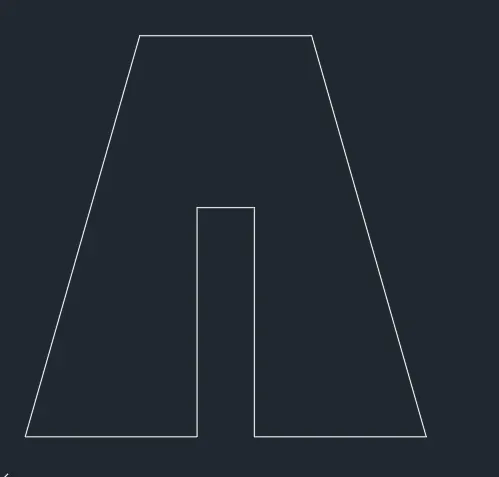
- Drafting the geometry given in p4
using relative coordinate system
- Select the line tool by entering LINE command in the command tab
- Specify the starting coordinates of point 1as 2,1 in the command line.
- Next coordinate @1,0.
- @0,4
- @2,-2
- @2,2
- @0,-4
- @1,0
- @0,7
- @-1,0
- @-2,-2
- @-2,2
- @-1,0
- Click close on the command line.
Result:

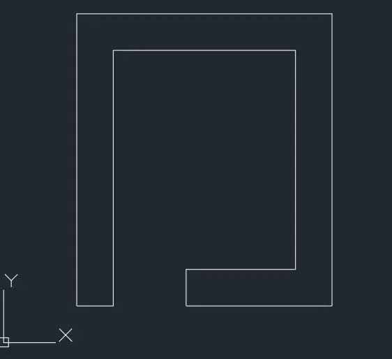
Drafting the geometry given in the p5
using relative coordinate system
- Select the line tool by entering LINE command in the command tab
- Specify the starting coordinates of point 1as 2,1 in the command line.
- Next coordinates @1,0
- @0,7
- @5,0
- @0,-6
- @-3,0
- @0,-1
- @4,0
- @0,8
- @-7,0
- Click close on the command line.
Result:
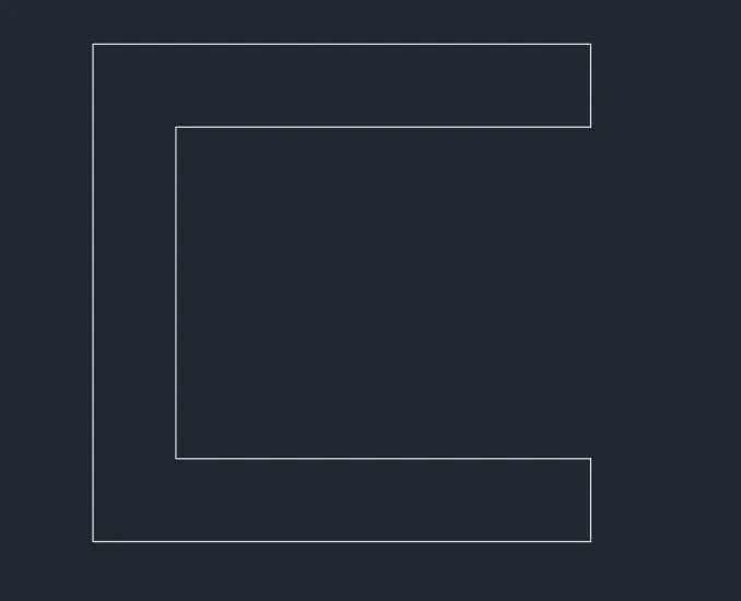
Drafting the geometry given in the p7
using relative coordinate system
- Select the line tool by entering LINE command in the command tab
- Specify the starting coordinates of point 1as 2,1 in the command line.
- Next coordinate @8,0
- @0,6
- @-8,0
- Click close on the command line
- Specify the starting coordinates of point 6 as 3,2 in the command line.
- @2,0
- @0,3
- @-2,0
- Click close on the command line
- Specify the starting coordinates of point 10 as 6,2 in the command line.
- @2,0
- @0,3
- @-2,0
- Click close on the command line.
Result:
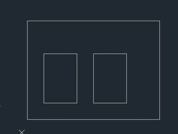
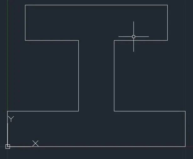
Drafting the geometry given in the p8
using relative coordinate system
- Select the line tool by entering LINE command in the command tab
- Specify the starting coordinates of point 1as 0,0 in the command line.
- Next coordinate @10,0
- @0,2
- @-4,0
- @0,4
- @3,0
- @0,2
- @-8,0
- @0,-2
- @3,0
- @0,-4
- @-4,0
- Click close on the command line.
RESULT:
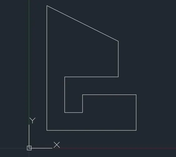
Drafting the geometry given in the p9
using relative coordinate system
- Select the line tool by entering LINE command in the command tab
- Specify the starting coordinates of point 1as 1,1 in the command line.
- Next coordinate @5,0
- @0,2
- @-3,0
- @0,-1
- @-1,0
- @0,2
- @3,0
- @0,2
- @-4,2
- Click close on the command line.
Result:
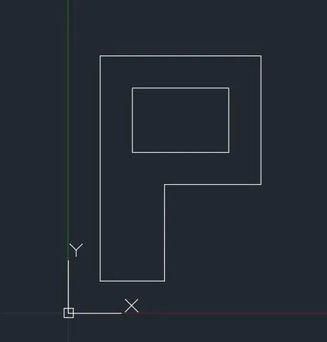
Drafting the geometry given in the p10
using relative coordinate system
- Select the line tool by entering LINE command in the command tab
- Specify the starting coordinates of point 1as 1,1 in the command line.
- Next coordinate @2,0
- @0,3
- @3,0
- @0,4
- @-5,0
- Click close on the command line.
- Specify the starting coordinates of point 8 as 2,4 in the command line.
- @3,0
- @0,2
- @-3,0
- Click close on the command line.
Result:
Drafting the geometry given in the profile wood
using relative coordinate system, relative polar system
- Select the line tool by entering LINE command in the command tab
- Specify the starting coordinates of point 1as 0,0 in the command line.
- Next coordinate @10,0
- @0,1
- @-2,0
- @0,4
- @2,0
- @0,1
- @5.831<149.036
- @5.831<210.964
- @2,0
- @0,-5
- @-2,0
- Click close on the command line.
- Select the circle tool by entering CIRCLE command in the command tab
- Specify the starting coordinate points as 5,4 in the command line
- Specify the radius as 2 in the command line
RESULT:
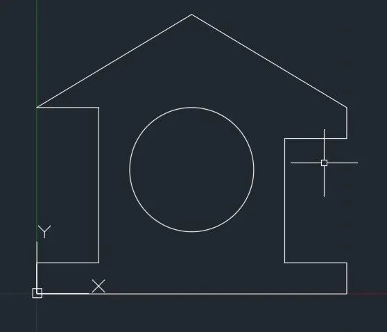
Draw the geometry given in the queen post truss
using relative coordinate system, relative polar system
- Select the line tool by entering LINE command in the command tab
- Specify the starting coordinates of point 1as 1,1 in the command line.
- Next coordinate @0,4
- @1,0
- @2.536,0
- @2.536,0
- @1,0
- @0,-4
- Specify the starting coordinates of point 8as 1,4 in the command line.
- @5<45
- @5<315
- @-1,0
- @0,1
- @-2.536,-1
- @-2.536,1
- @0,-1
Result:
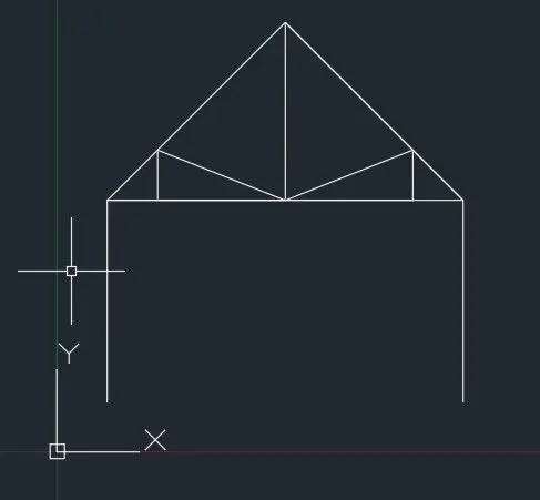
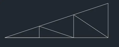
Draw the geometry given in the mono pitch
using relative coordinate system, relative polar system
- Select the line tool by entering LINE command in the command tab
- Specify the starting coordinates of point 1as 1,1 in the command line.
- Next coordinate @2,0
- @2,0
- @2,0
- @0,2
- Click close on the command line
- Specify the starting coordinates of point 7as 2,0.667 in the command line.
- @2,-0.667
- @0,1.333
- @2,-1.333
Result: