Reinforcement Detailing of Beams from ETABS output
AIM & INTRODUCTION :
AIM :
- To create a detailed design of concrete building by Running the analysis and designing the RCC Moment ResistingFrame specifically with two continuous beams in the 1st floor.
INTRODUCTION :
- In E-TABS the stuctural members such as beams, columns and slabs can be created and analysed its bending moment and shear force.
- We can Run the Concrete Frame Design fo the created structure to provide required both Longitudinal and shear reinforcement bars automatically.
- The values for the created structures can be automatically calculated by E-TABS.
- Here in E-TABS we can know the number of Reinforcement bars should be provided for the concrete structures.
- From Frame design analysis we can see both Top and Bottom reinforcement figures for each beam sections.
- Also we can display concrete frame design result for Shear reinforcement.
- Moreover we can view the concrete beam design information as per IS 456:2000.
- The Design details of the overall structures can also be viewed as Summary, Flexural Details, Shear Details, Envelope.
PROCEDURE :
- Open the Delivered E-Tabs file from the attachment with Base, ground, first, second, third, terrace and mumty level.
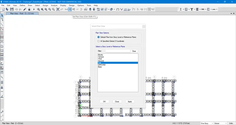
- After opening of the file click the plan tool and from select plan view tab click and select First floor level and click OK.
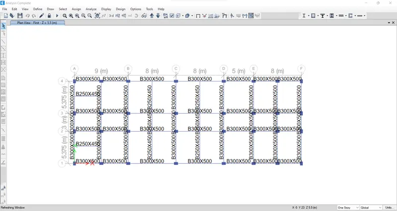
- Then we can see the beam size of 300x500 in all the grids from 1 to 4 and A to F with varying span length.
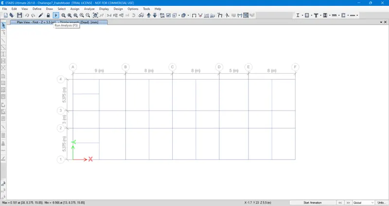
- Now click Run Analysis tool to start analyse the opened file.
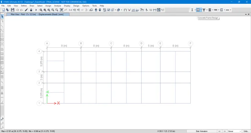
- After the Analysis of the E-Tabs file we need to create a concrete frame design for all the beams.
- For that click the option present in the Tool bar above the E-Tabs workspace to create a Concrete Frame Design.
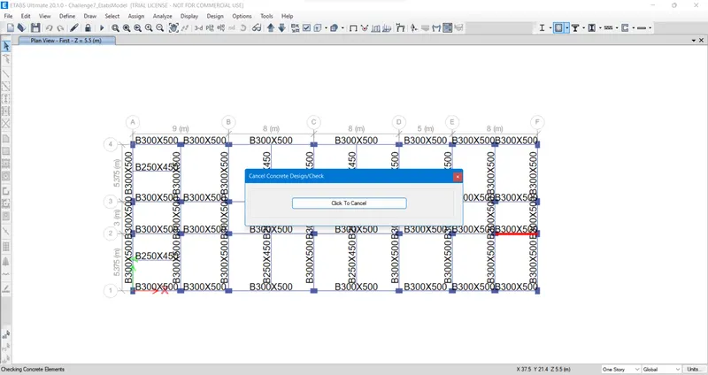
- Then we can see the concrete Design check Tab opened while creating Concrete frame and asking for the cancellation
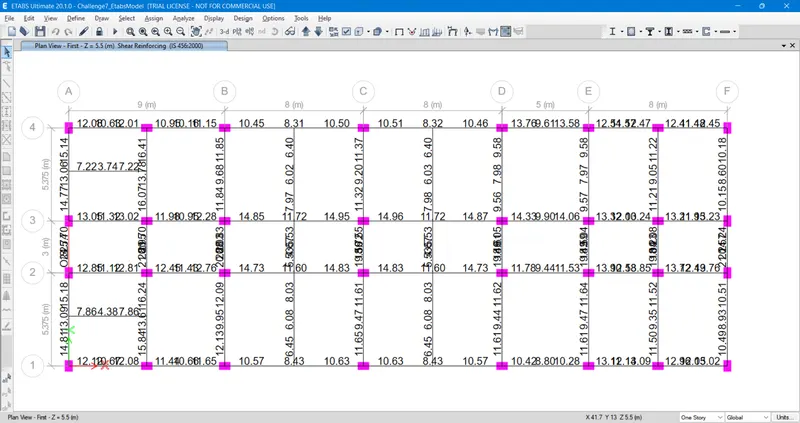
- After the completion of the frame designing, we can see the reinforcement requirement for the every span of the beams.
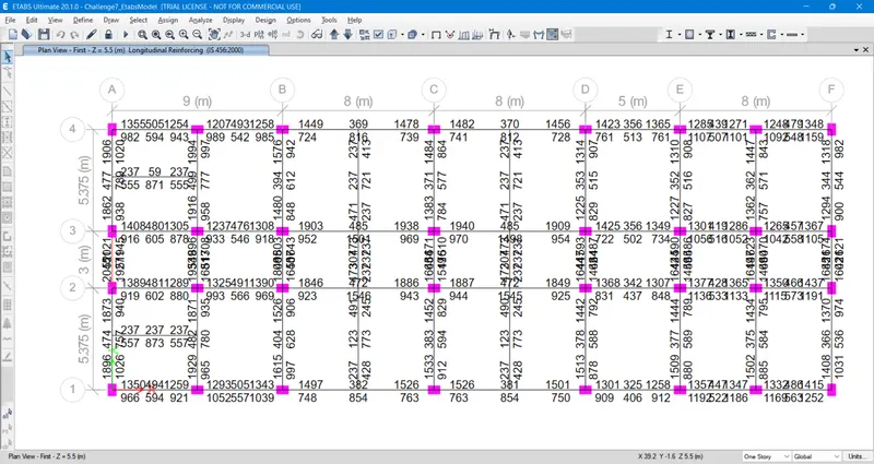
- These required reinforcement is provided for End top, End Bottom, Mid top, Mid bottom of the beams.
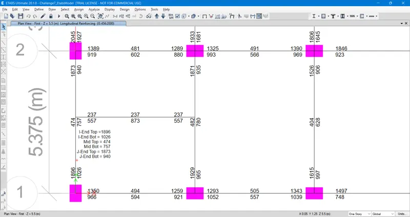
- Here, we can see the Shear reinforcement of the beams as well as Longitudinal reinforcement of the beam.
- For that click the downward arrow present near the concrete frame design tool and Select Display Design Information.
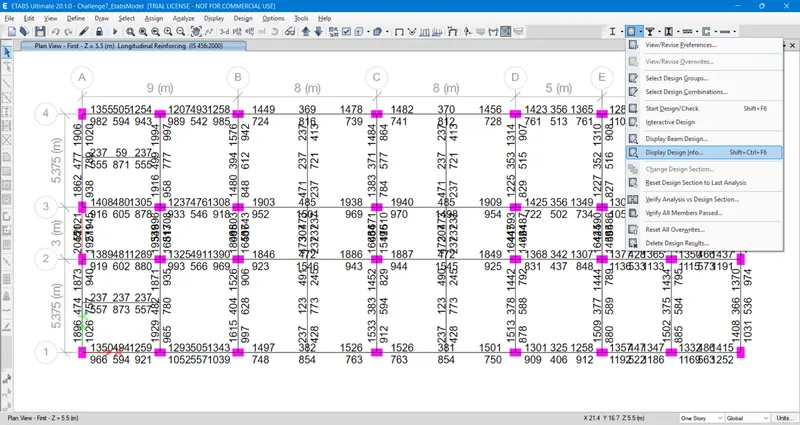
- After the selection of the Display design Information, the Display concrete frame design Result Tab will be opened.
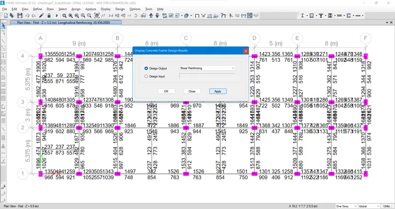
- From the Design Output select the Downward arrow and then select the shear reinforcement.
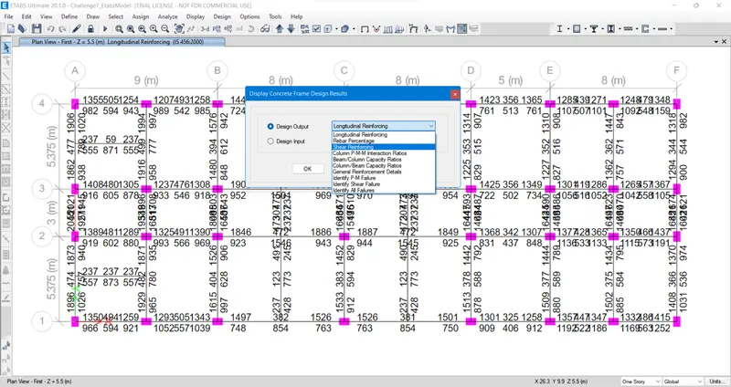
- Then click Apply to see the reinforcement requirement for the shear demand of the beams.
- Now, after applying the design output as Shear reinforcement we can see the Mid,Top's end and bottom required reinforcements.
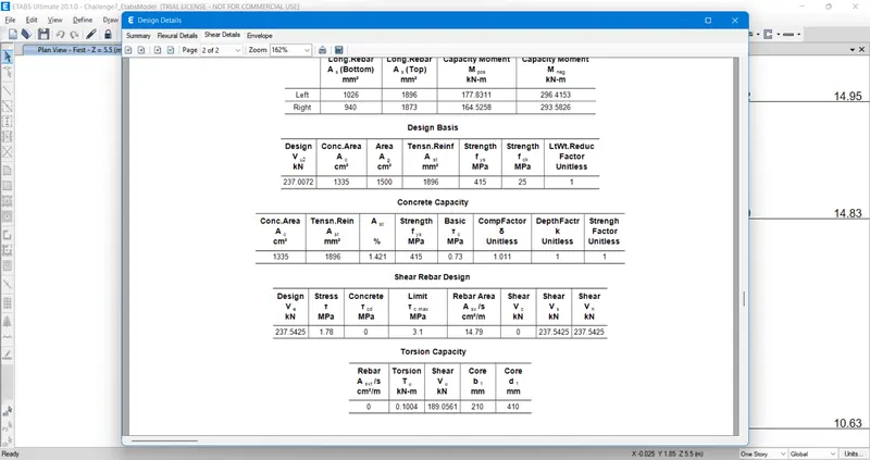
- To see the Design details of any one of the beams created in Shear reinforcement.
- Right click on any beam and we can see the Concrete beam design information Tab is opened.
- From there click Details to check the Designs of the shear details.
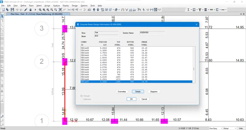
- The Design check tab will be opened, then click the Shear Details menu present at the Menu bar.
- There we can see all the shear details of the beams created.
RESULT :
1) 3 span continuous beam along grid A :
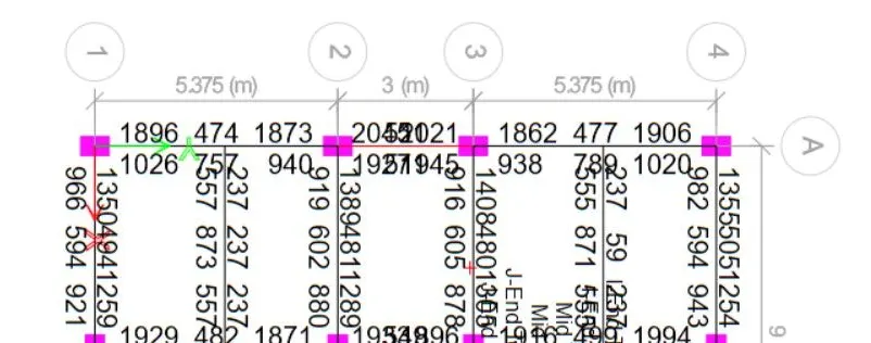
2) 7 span continuous beam along grid 3 :

Addressed the following issues below :
A ) Provided the details of longitudinal and shear reinforcement for the two continuous beams :
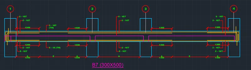
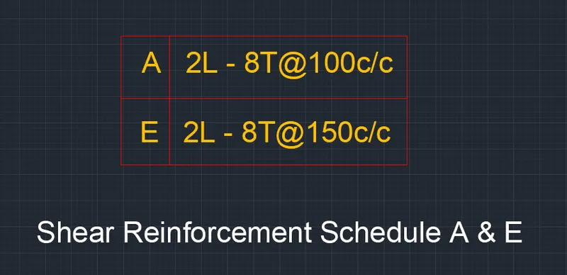
B ) Provided the reasons for failure of the middle span along grid A and the possible ways to resolve this issue :
MID SPAN ALONG GRID A :
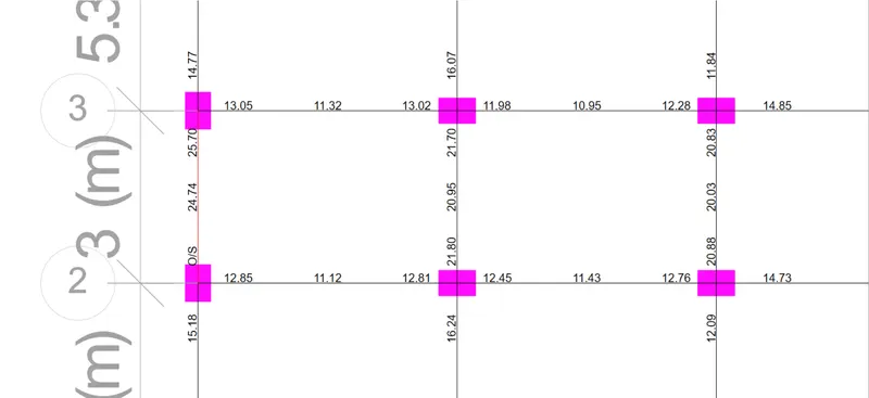
- The mid span along Grid A is failed due to it is Over stressed.
- It means it is violated the code values for shear reinforcement for shorter span beams.
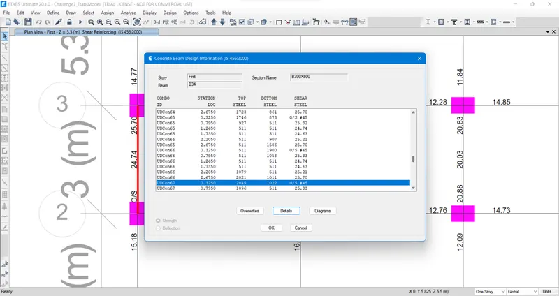
- Now right click on the Over stressed mid span to open the new tab named the concrete beam design information (IS 456 2000).
- In this opened tab we can see the shear steel was not calculated for 3 combinations .
- Then select and click the over stressed beam and click Details button to view the Details it.
- From the Design Details tab we can see that it shows 'O/S #45 Shear stress due to shear force and torsion together exceeds maximum allowed '
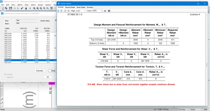
- Shear stress is nothing but Load/Area.
- So we have to Reduce the loading or Increase the Area to get rid of these over stresses.
- The shear capacity of the concrete it varies with respect to the grade of concrete.
- Instead of the default M25 graded concrete used for the entire model we can use some higher grade for this beam alone like M30, M35, M40 etc.
- By this we can increase the shear capacity for the beam and therefore we can make it pass in the shear stress design
C ) Calculate value of the maximum shear force in any one of the spans in both the continuous beams, as per clause 6.3.3 (b) in IS 13920 – 2016 :
a. SWAY SHEAR FORCE TO RIGHT :
i. `V_u,_a = V_u,_aD^+L` - 1.4 `frac{M_u ^As + M_u^Bh} {L_AB}`
Given :
`M_as = 174 kNm`
`M_bh = 293 kNm`
`L_ab = 4.725 m`
`V_d +_l = 92 kN`
Solution :
or
`V_u,_a = 92` - 1.4 `frac{174 + 293} {4.725}`
`V_u,_a = 46 kN`
ii. `V_u,_ab = V_u,_bD^+L` + 1.4 `frac{M_u ^As + M_u^Bh} {L_AB}`
Given :
`M_as = 174 kNm`
`M_bh = 293 kNm`
`L_ab = 4.725 m`
`V_d +_l = 92 kN`
Solution :
`V_u,_a = 92` + 1.4 `frac{174 + 293} {4.725}`
`V_u,_a = 230 kN`
b. SWAY SHEAR FORCE TO LEFT :
i. `V_u,_a = V_u,_aD^+L` - 1.4 `frac{M_u ^Ah + M_u^Bs} {L_AB}`
Given :
`M_ah = 234 kNm`
`M_bs = 155 kNm`
`L_ab = 4.725 m`
`V_d +_l = 70 kN`
Solution :
`V_u,_a = 70` - 1.4 `frac{234 + 155} {4.725}`
`V_u,_a = 185 kN`
ii. `V_u,_b = V_u,_bD^+L` + 1.4 `frac{M_u ^Ah + M_u^Bs} {L_AB}`
Given :
`M_ah = 234 kNm`
`M_bs = 155 kNm`
`L_ab = 4.725 m`
`V_d +_l = 70 kN`
Solution :
`V_u,_a = 70` + 1.4 `frac{234 + 155} {4.725}`
`V_u,_a = 45 kN`
THE SWAY - SHEAR RESULT :
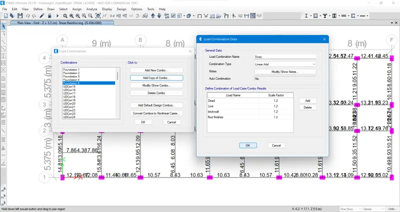
Open Load Combination by clicking Define < Load Combination.
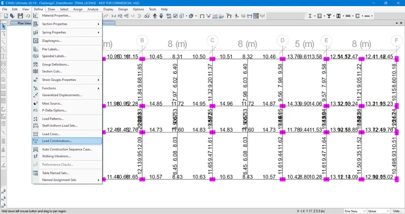
- Then Click existing load combination and select 'Add copy of combo'.
- Here we can see the opened Load Combination Data Tab.
- In this opened tab, change 'Load combination Name = Sway'.
- Now make scale factor for all the Loads as 1.2 and click OK.
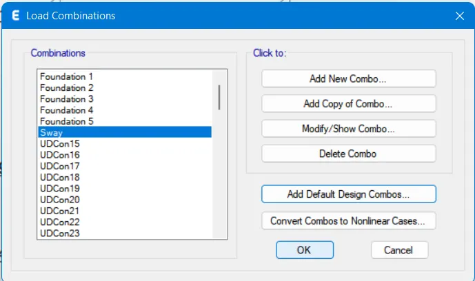
- After providing the Load combination Data, we can see the created Load combination at the Load Combination List.
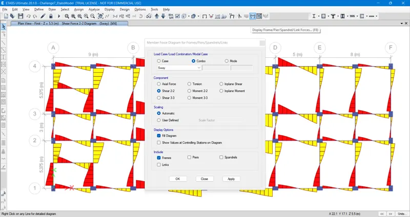
- Atlast to see the E-tabs calculation of shear force demand through Shear force Diagram.
- For that Click 'Display Frame' tool present at the Tool bar to open the 'Member Force Diagram Tab'.
- After the opening of the Tab click Combo < Shear 2-2 and select OK to see the E-tabs calculated sway values as shear diagram.
EXISTING SHEAR CAPACITY IN BEAM AS PER DRAWING (AS PER IS-456 2000 CLAUSE 40.4) :
iii. `V_us = frac{0.87 fy A_sv d}{S_v}`
Given :
`Fy = 415 Nmm^2`
`A_sv = 151 mm^2`
`d = 450mm`
`Sv = 100mm`
Solution :
`V_us = frac{0.87 (415 x 151 x 450)}{100}`
`V_us = 245 kN`
Hence shear rebar in drawing is okay as per IS - 13920 code guideline.