Reinforcement Detailing of Beams from ETABS output
Aim:
To design the beams in detail from the etabs
To provide details of longitudinal and shear reinforcement for the given two continous beams
To calculate the value of maximum shear force in any one of the spans in the continous beams
Introduction:
A Beam is a horizontal structural element that runs horizontally to withstand vertical load coming off the building frame. The beam takes the load & distributes it to ends and transfers it to columns, walls, and posts on both sides of the beam. it only withstands laterally applied loads on the axis of the beam.
When the shear stress on an object exceeds the maximum permissible shear stress, then the object undergoes a failure known as shear failure. Shear failure can be defined as a failure that takes place due to insufficiency of shear resistance available between the materials.
The flexural strength represents the highest stress experienced within the material at its moment of rupture. It is measured in terms of stress. To overcome this type of failure, main steel is provided at the bottom/top of the beam. Flexural failure occurs at mid-span of beam
To prevent failure in the beam, there are some points below
- According to the size of the beam, steal bars having diameter like 12mm, 16mm etc.
- Extra bars should be provided.
- Proper spacing must be necessary.For example, at some distance from junctions, stirrups having less spacing as compare to more spacing at central portion to prevent shear failure.
- Concrete mix design must be necessary and during casting, proper vibrator should be operated to avoid voids.
- Development length should be proper according to drawing.
Procedure:
STEP 1
First open the challange 7 page and download the model
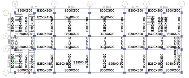
After downloading the challenge, open it in etabs as shown in the picture below
STEP 2
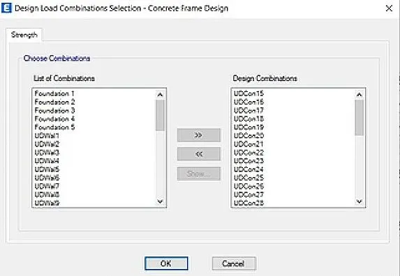
Now check the load combinations as shown below
STEP 3:
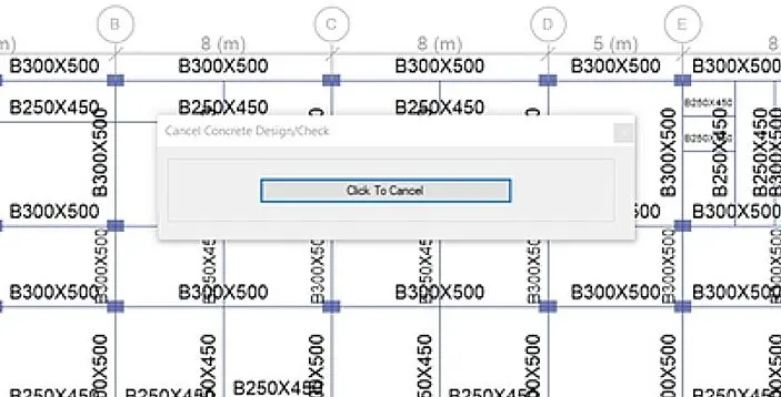
Next we have to start the beam design by selecting the Start design/ check” as shown below

The design/check process will start
STEP 4:
After the completion of the beam design, we need to select the “Display Design Info” option as shown below
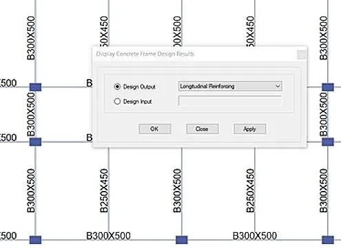
After selecting the “Display Design Info” option the new tab appears, in that we select the longitudinal reinforcing in the design output and click on the OK button, as shown below
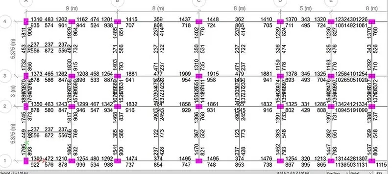
Next the longitudinal reinforcement details will appear, as shown below
STEP 5:
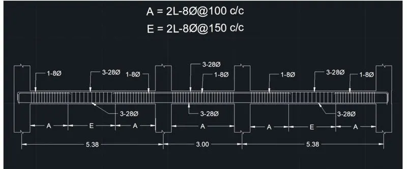
Next we need to draw the reinforcement diagram of 3 span continous beam along Grid A and also need to provide the reinforcement details
The maximum Ast for the bottom support is 1766 `mm^2`
And bottom middle is 702 `mm^2`
The max Ast for top support is 1889 `mm^2`
And top middle is 453 `mm^2`
Now we provide 3-28 `phi`
At the top and bottom as shown in the below figure
Next we provide 1-8 `phi` at the top supports for the continous beam, as shown below
STEP 6:
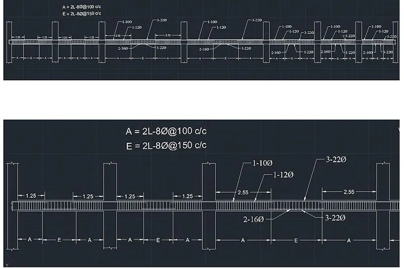
Next we need to draw the reinforcement diagram of 7 span continous beam along grid 3 and also need to provide the reinforcement details
The max Ast for the bottom support is 1061 `mm^2`
And bottom middle is 1493`mm^2`
The max Ast for the top support is 1915`mm^2`
And the top middle is 479`mm^2`
Now we provide 3-22`phi`
At the top and bottom , as shown in the below figure
Next we provide 1-10`phi` and 1-12`phi`
At the top supports and provide 2-16`phi`
At the bottom middle for the continous beam, as shown below
STEP 7:
After providing the beam reinforcement details we select the beam and right click on the beam then the new tab appears as shown below
Next we need to click on the details option in concrete beam design tab as shown below
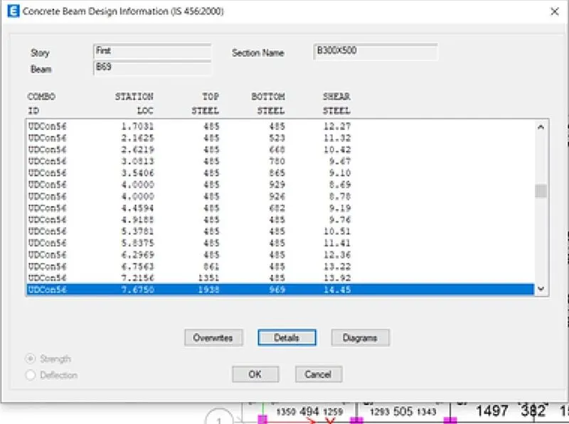
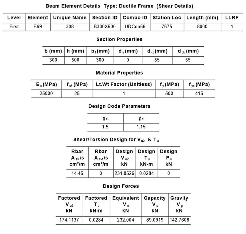
Next the shear details will be visible as shown below
As per the clause 6.3.3 the design force is 232 KN
We got, max shear force = 174.11 KN
RESULT:
The beams are designed successfully in detail from the Etabs software
Provided the details of longitudinal and shear reinforcement for the two continous beams
And also calculated the value of max shear force in the continous beams using the Etabs software.