Reinforcement Detailing of Beams from ETABS output
Detailed design of beams in Etabs 2018.
The ETABS file for a G+4 building is provided. Run the analysis and design the RCC Moment ResistingFrame. The following challenge deals specifically with two continuous beams in the 1st floor.
1) 3 span continuous beam along grid A
2) 7 span continuous beam along grid 3
ANSWER:
COMPLETE STEPWISE PROCEDURE TO DESIGN MULTI-SPAN CONTINUOUS BEAMS IN ETABS
- Open the ETABS Model for Which you Want to Design the Beams
- Double click on ETABS or search it up from the start menu and open the software.
- Now, look for the file that contains the building model that needs to be designed.
- In our case, the building model has already been attached to the question.
- So, we downloaded it to the system and then opened the same using ETABS.
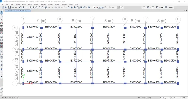
- Run the Analysis
- Before designing any structural member, we first need to have the analysis results and the area of reinforcement required at different sections of the building.
- So, we need to first analyze the model before going ahead with the design bit.
- And to run the analysis in ETABS, you can simply press the F5 button on your keyboard or you can also click on the play button available in the front tool ribbon in the software.
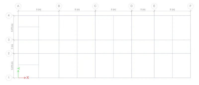
- Run the Frame Design
- Now that the analysis is complete and the structural results are available, you can run the design in ETABS.
- However, before running the frame design, you need to check for a few things that are listed below.
- You need to check if the proper design codes are implemented for the frame design.
- And we can check this from the view/revise reference option within the frame design dropdown list.
- You can set the design code which you want to follow for the particular building.
- So, we have elected the IS-456 for the R.C.C frame design in our case.
- And there are also various other options available in this list which you can adjust as per your design.
- And once you have viewed this design reference, you're all set to go ahead and design the frame for your model.
- So, just click on the frame design logo available on the right-hand side toolbox in ETABS.
View/Revise Reference
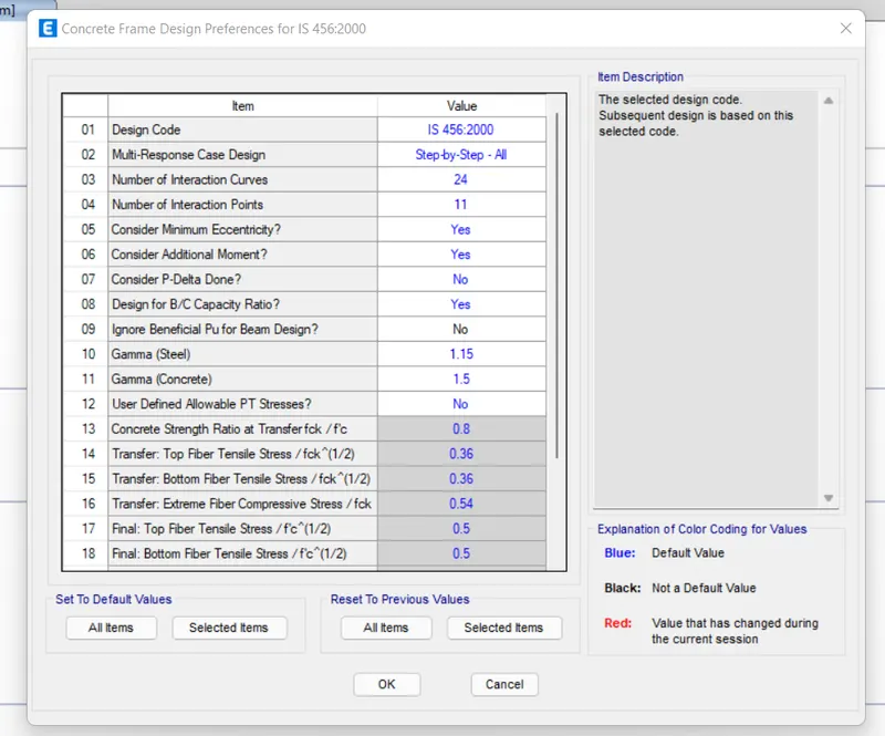
Concrete Frame Design Option
Design Completed
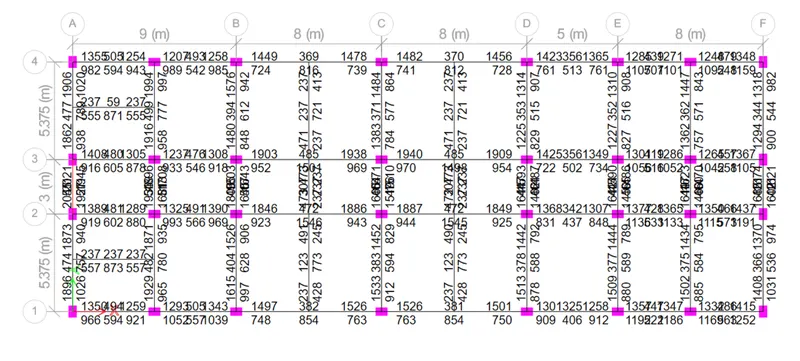
- Understanding the ETABS Output
- After completing the design in the ETABS as explained above, the software displays various results based on the section and material properties of your model.
- So, one must be able to properly comprehend the design results in order to design a safe and sound structure.
- As we're talking about the beams, ETABS tells you the amount of reinforcement needed at different beam sections in millimeter squares.
- And as we know there are primarily two kinds of reinforcement provided in beams that are longitudinal and shear.
- So, the ETABS provides data regarding the area of steel required for top and bottom longitudinal bars as well as the area of steel needed for the shear reinforcement of the beam.
- Accordingly, the beam reinforcement is to be designed as per the area of steel provided in the ETABS output.
- And the same is carried out in the following sections of this assignment.
Designing the Beams
1. Seven-Span Continuous Beam Along Grid-3
- Span One
- First, look at the maximum Ast given by software for both the top and bottom longitudinal bars.
- In our case, the maximum reinforcement for the top is the area of 1940 millimeter squares, and the same for the bottom is 1504 millimeter squares.
- So, based on the above results, we provide 2-T32 and 1-T25 bars at the top which sums up the total 2098 mm^2. Hence OK.
- And for the bottom portion, we provide 2-T32 bars accounting for 1608 mm^2 Ast which is more than the required in our case. Hence OK.
- Now, we need to calculate the curtailment length for the bar as the reinforcement needed at the center of the beam is much less.
- And according to the codes, we take L/3 as the standard curtailment length on either side of the beam.
- Thus, for span one, we take 1300mm using the L/3 formula.
- Now, we need to calculate the development length for tensions as well as the compression bars.
- As per IS-456, development length is given by "bar dia. x sigma s / 4 x tau bd.
- Furthermore, to obtain the total anchorage length, we need to add the above value with 10 x the bar dia.
- However, since we are providing a 90 degrees bent, we need to deduct the 8dia value from the anchorage length obtained in the above step.
- So, following the same procedure, the anchorage length was found to be 47d for bars in tension and 38d for bars in compression.
- Now, we need to allow the size and number of bars needed for the shear reinforcement.
- And to do that, provide 2-legged 8mm dia bars as vertical stirrups.
- The shear reinforcement near supports shall be closely spaced up to the length of twice the development length.
- The spacing near the supports shall not be less than 100mm in any case.
- So, the required calculations were done and the shear bars were provided in the beam for span one as shown below:
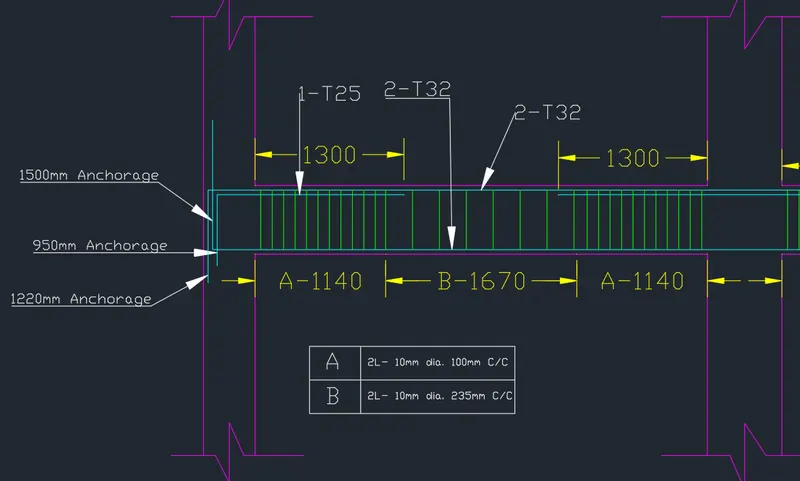
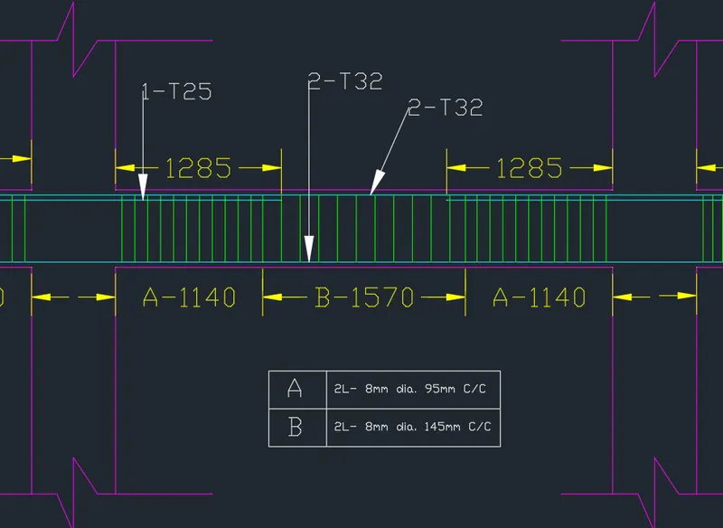
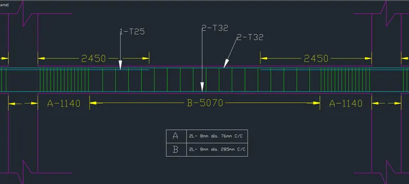
So, following the same standard procedure as discussed above, the remaining spans of the beam were designed and the final drawings are inserted as follows:
- Span Two
- Span Three
- Span Four
- Span Five
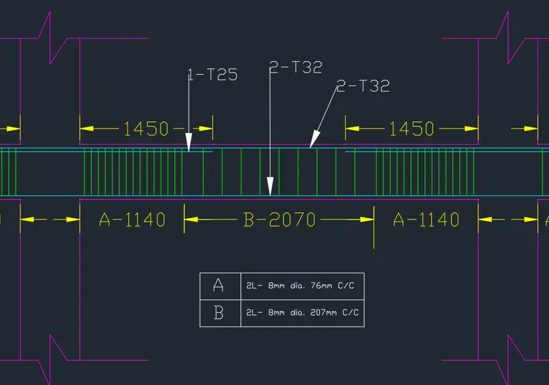
- Span Six
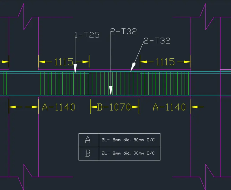
- Span Seven
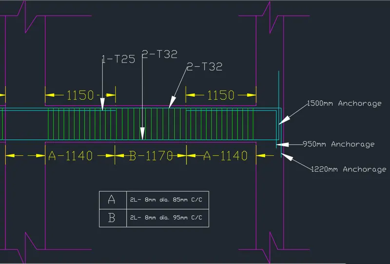
FINAL OUTPUT:

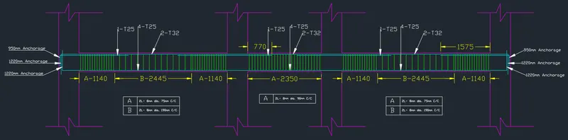
2. Three-Span Continuous Beam Along Grid-A
- Span One
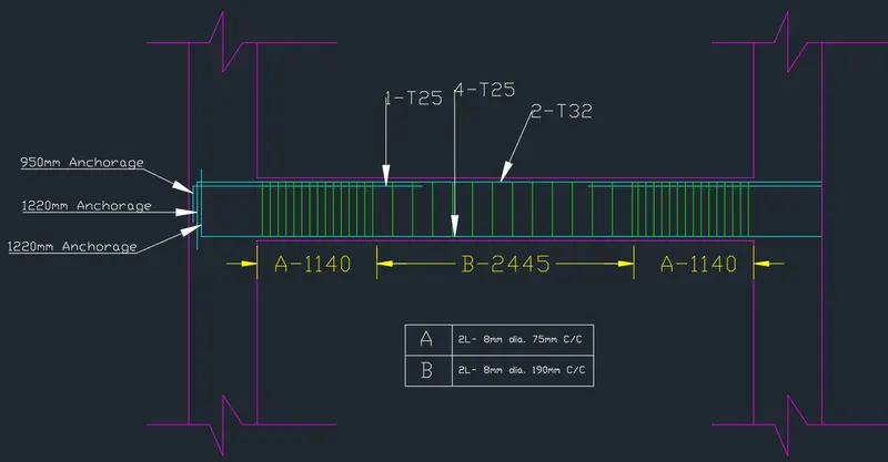
- Span Two
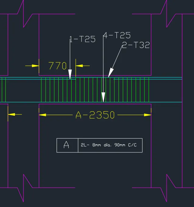
- Span Three
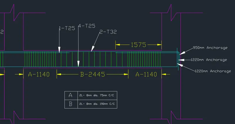
FINAL OUTPUT:
Design Related Q&A:
• Provide reasons for the failure of the middle span along grid A. What are the possible ways this issue can be resolved?
ANSWER:
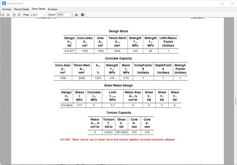
The reason why the middle span along gird A fails is due to the overstressing in shear near the right support. The shear stress given by the ETABS analytical model at that particular span exceeds the corresponding limiting value as stated by the design codes. Accordingly, the ETABS detailed section also gives the reason for the failure of the span which is shown in the below image.
Possible ways to resolve this issue:
As we know that shear stress is the factor of shear force and the sectional dimensions of the beam. Hence, the overstressing of shear can be resolved in two ways as listed below:
- The shear stress can be controlled by increasing the beam dimensions that are b and d. If we increase the value for b and d for that particular beam span, the nominal shear stress can be reduced and brought back within the limiting value.
- The second way to counter this problem is by reducing the live load on the structure. When you reduce the live load for this span, the net shear force will also reduce making the section pass the design without failing.
• Calculate the value of the maximum shear force in any one of the spans in both the continuous beams, as per clause 6.3.3 (b) in IS 13920 – 2016. Also, confirm these values from the shear force demand calculated by ETABS. Please note that if longitudinal reinforcement provided is more than required (as per ETABS results), the shear force demand will vary from what is provided by ETABS.
ANSWER:
As per clause 6.3.3, the shear reinforcement provided in the beam must be able to take up the maximum sway shear induced for the same section. At the same time, part (b) of clause 6.3.3 also mentions the formula to obtain the sway shear in both directions that are left and right which is given as follows:
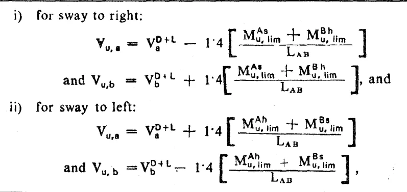
So, using the above formula, we have calculated the sway shear as given below:
However, we need to first calculate the shear force at supports due to the factored gravity loads in order to arrive at the values for Va(D+L) AND Vb(D+L). So, we have added a new load combinatin with dead and live gravity loads with the safety factor 1.2 as mentioned in the IS-code.
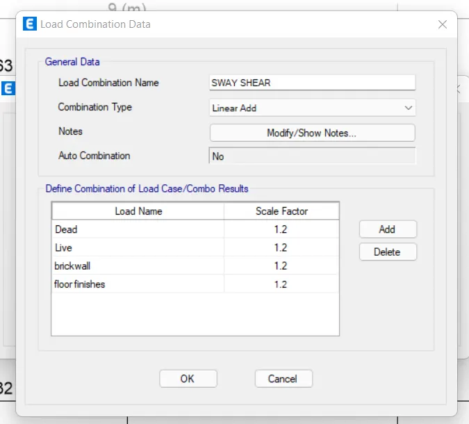
Now we can insert the relevant values and obtain the sway shear values as follows:
Sway to the Right
- Vua = 46 KN
- Vub = 230 KN
Sway to the Left
- Vua = 185 KN
- Vub = 45 KN
So, the maximum shear among the four values is of 230 KN. Therefore, the stirrups designed for this beam must be able to resist more than 230KN of shear force for a safe beam design. Thus, let's check how much our stirrups can take in terms of the shea force.
Shear Taken by Stirrups, (Vus):
Vus = 0.87fy Asv d / Sv
= 0.87x500x100x570 / 75
Vus = 330 KN
Since, 330KN>230KN. Thus, our shear design is safe.