Reinforcement Detailing of Beams from ETABS output
AIM; Design of beam provided in model.
provide the longitudinal and shear reinforcement for the continous beam provided in the model.
open the attachment
check load combination
run analysis.
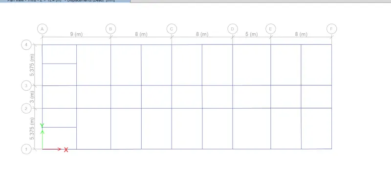
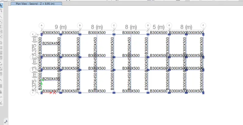
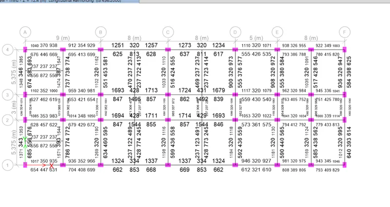
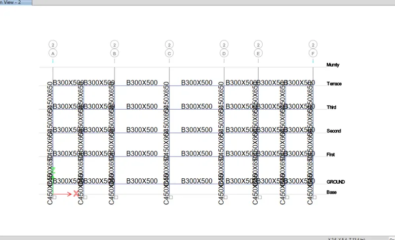
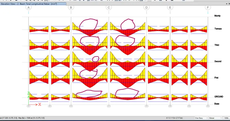
REINFORCEMENT DETAILS OF 7 SPAN CONTINOUS BEAM ALONG X AXIS
| Beam no | Top rebar | Bottom rebar | SHEAR link | |
| B29,B28,B27,B30,B31,B78,B79 | 3#25MM@100MM | 3#20MM@100MM | 8MM@100MM | FROM COLUMN FACE TO 2D |
| B31, B30 ,B78,B79 | 3#20MM@100 | 8MM@150 | MIDDLE OF COLUMN | |
| B28,B32 | 3#25MM@100MM | |||
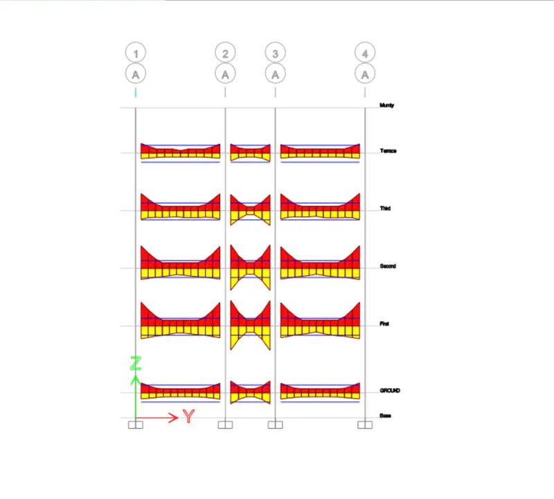
3 span continous beam along grid A
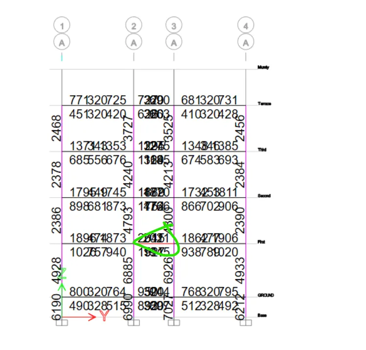
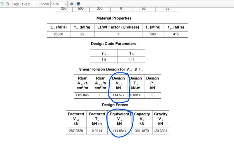
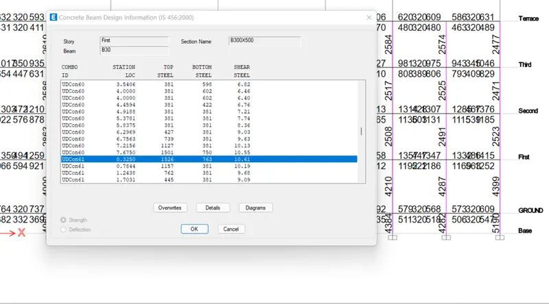
here the shear fore is high.
This failure beam no is B34
bottom longitudinal barr should be 50% of top longitudinal rebar as per clause 1s 13920 6.2.3
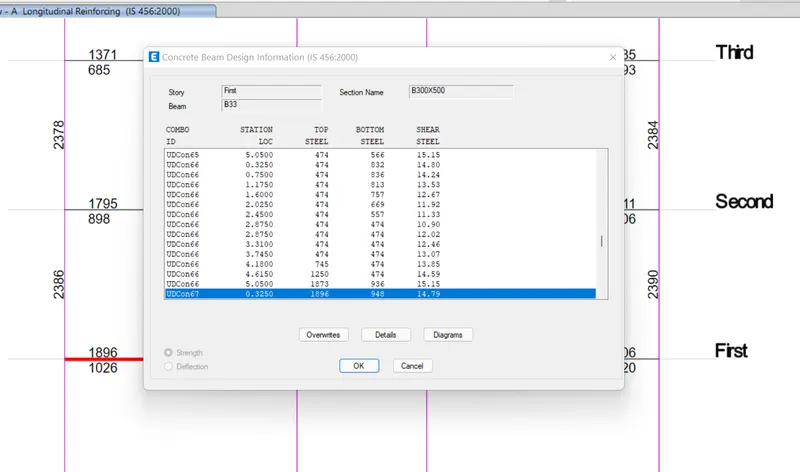
| BEAM NO | TOP REBAR | BOTTOM STEEL | LINK |
| B33,B38, | TWO LAYER 3#20MM | 3#20 | TWO LEGGED 8MM@100 |
shear force in any span.
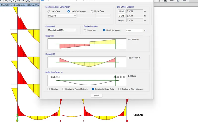
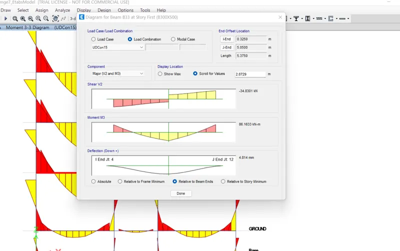
maximum shear V2 = 103.0079
moment Mh=80.30
moment Ms= 86.133
Clear span=5.3750
V1=103.0079 -(80+86.13)/5.375 = 72.