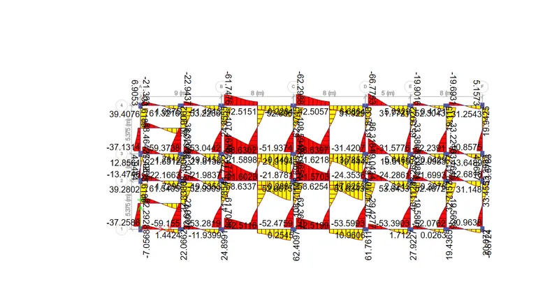
Reinforcement Detailing of Beams from ETABS output
Challenge 8
The ETABS file for a G+4 building is provided. Run the analysis and design the RCC Moment ResistingFrame. The following challenge deals specifically with two continuous beams in the 1st floor.
1) 3 span continuous beam along grid A
2) 7 span continuous beam along grid 3
Address the following issues thereafter.
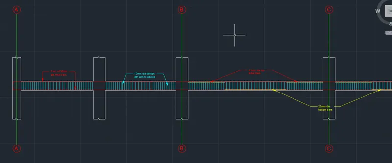
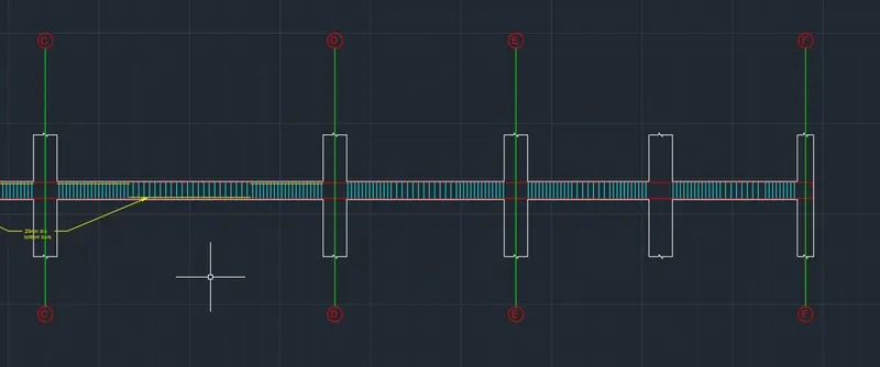
- Provide details of longitudinal and shear reinforcement for the two continuous beams. Sketch the beam elevation details or draft it using autocad software.
-
Provide reasons for failure of the middle span along grid A. What are the possible ways this issue can be resolved?
-
Calculate value of the maximum shear force in any one of the spans in both the continuous beams, as per clause 6.3.3 (b) in IS 13920 – 2016. Also, confirm these values from shear force demand calculated by ETABS.Please note that if longitudinal reinforcement provided is more than required (as per ETABS results), the shear force demand will vary from what is provided by ETABS.
ANSWERS:-
AIM:-Run the analysis and design the RCC Moment ResistingFrame.
- 3 span continuous beam along grid A
- span continuous beam along grid 3
PROCEDURE:-
STEP 1:
- Download the given G+4 etabs building and open it in the Etabs software.
- Check the model.

- Now go run the analysis.
STEP 2:
- Now go to concrete frame design>select design preferences.
- Keep all the settings as such in the window and then click ok.
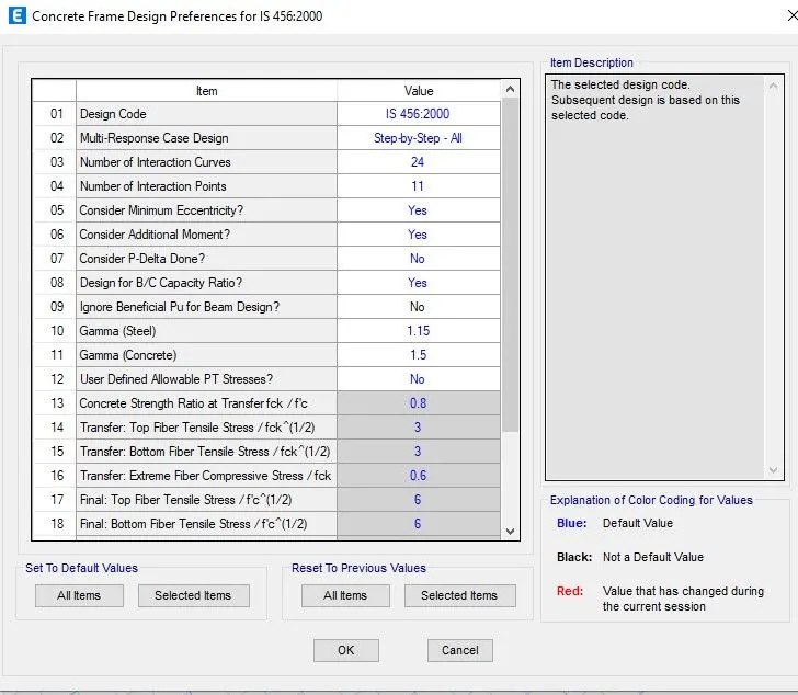
- Now go to Design combinations and click ok.
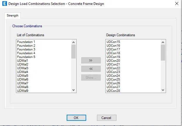
- Click on concrete frame design for design check.
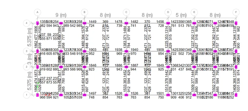
- Now go to concrete frame design>Display design info.
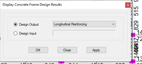
- In the dialogue box that appears change the settings to longitudinal reinforcement as the design output>Ok.
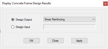
- Now change the settings as shear reinforcement.
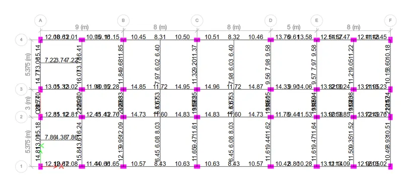
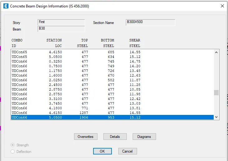
- For the beam reinforcement information,right click on members.
Step 3:-
A.Provide details of longitudinal and shear reinforcement for the two continuous beams.
Table of longitudinal and shear reinforcement for the continous 3 span beams along Grid A
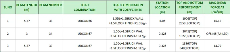
Beam 38

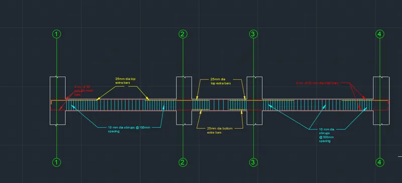
- Provding 2 nos of 32mm dia longitudinal bars are provided at top and bottom of the beam throghout the span.
- Also provide 1 extra 25 mm bars at right end and left end on top of these sections.(No extra bars at the bottom)
Beam 34

- Provding 2 nos of 32mm dia longitudinal bars are provided at top and bottom of the beam throghout the span.
- Also provide 1 extra 25 mm bars at right end and left end on both top and bottom of these sections.
Beam 33

- Provding 2 nos of 32mm dia longitudinal bars are provided at top and bottom of the beam throghout the span.
- Also provide 1 extra 25 mm bars at right end and left end on top of these sections.(No extra bars at the bottom).
Table of longitudinal and shear reinforcement for the continous 7 span beams along Grid 3
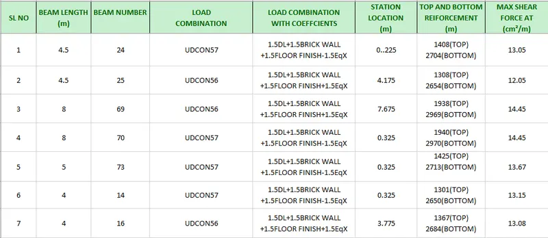
Beam 24

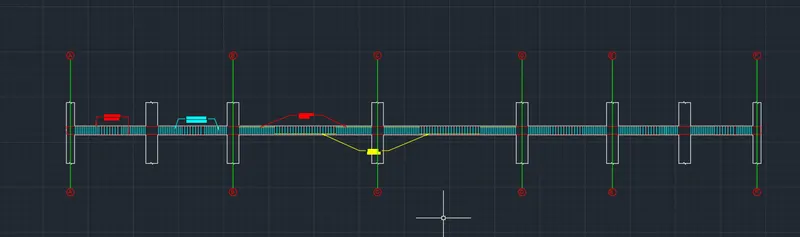
- Provding 2 nos of 32mm dia longitudinal bars are provided at top and bottom of the beam throghout the span.
- no extra bars required in this span,the main bars itself staisfies the reinforcement requirements.
Beam 25

- Provding 2 nos of 32mm dia longitudinal bars are provided at top and bottom of the beam throghout the span.
- no extra bars required in this span,the main bars itself staisfies the reinforcement requirements.
Beam 69

- Provding 2 nos of 32mm dia longitudinal bars are provided at top and bottom of the beam throghout the span.
- Also provide 1 extra 25 mm bars at right end and left end on the top section and 1 extra bars at mid span of bottom section.
Beam 70

- Provding 2 nos of 32mm dia longitudinal bars are provided at top and bottom of the beam throghout the span.
- Also provide 1 extra 25 mm bars at right end and left end on the top section and 1 extra bars at mid span of bottom section.
Beam 73

- Provding 2 nos of 32mm dia longitudinal bars are provided at top and bottom of the beam throghout the span.
- no extra bars required in this span,the main bars itself staisfies the reinforcement requirements.
Beam 14

- Provding 2 nos of 32mm dia longitudinal bars are provided at top and bottom of the beam throghout the span.
- no extra bars required in this span,the main bars itself staisfies the reinforcement requirements.
Beam 16

- Provding 2 nos of 32mm dia longitudinal bars are provided at top and bottom of the beam throghout the span.
- no extra bars required in this span,the main bars itself staisfies the reinforcement requirements.
Shear reinforcement detailing for grid A
Beam 38
Largets value of shear=242.75 KN with Load combination 66
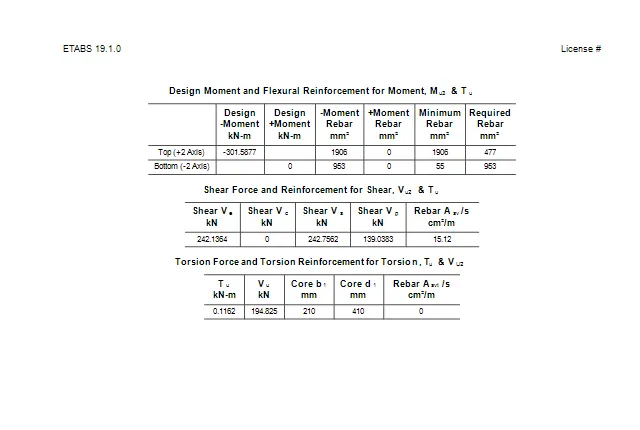
Least value of shear= 174.29 kN
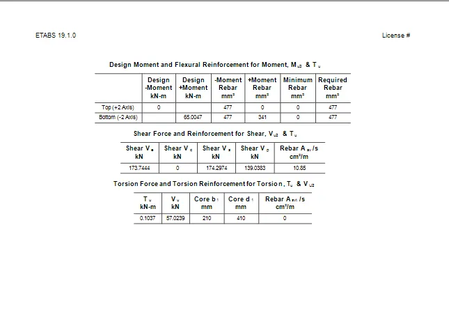
Trial and error method
1.Hence provide 2 legged 8 mm dia stirrups with 100mm spacing
Providing 30 mm clear cover
Check:-
- Vus = (0.87*Fy*Asv*D)/Sv
= (0.87*415*(2*π/4*8²)*(500-60))/100
= 159 KN < 242.75KN
2.Hence provide 2 legged 10 mm dia stirrups with 100mm spacing
Providing 30 mm clear cover
Check:-
- Vus = (0.87*Fy*Asv*D)/Sv
= (0.87*415*(2*π/4*10²)*(500-60))/100
= 249.54 KN > 242.75KN.
Hence safe .
=>So provide 2 legged 10 mm dia stirrups with 100mm spacing in grid 3.(Spacing can be increased in the mid sections of the beam)
Beam 24
Shear reinforcement detailing for grid 3
Largets value of shear=209.55 KN with Load combination 57
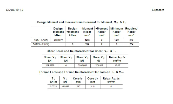
Least value of shear= 139.19 kN
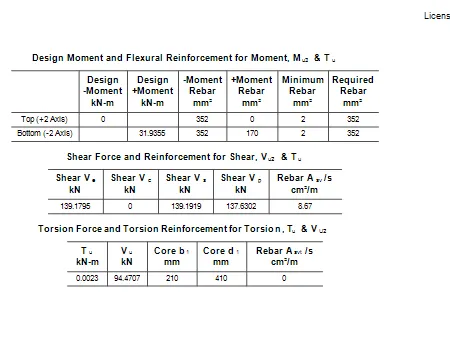
1.Hence provide 2 legged 10 mm dia stirrups with 100mm spacing
Providing 30 mm clear cover
Check:-
- Vus = (0.87*Fy*Asv*D)/Sv
= (0.87*415*(2*π/4*10²)*(500-60))/100
= 249.54 KN > 209.55 KN.
Hence safe .
=>So provide 2 legged 10 mm dia stirrups with 100mm spacing in grid 3.(Spacing can be increased in the mid sections of the beam)
Grid A
Grid 3
B.Provide reasons for failure of the middle span along grid A. What are the possible ways this issue can be resolved?
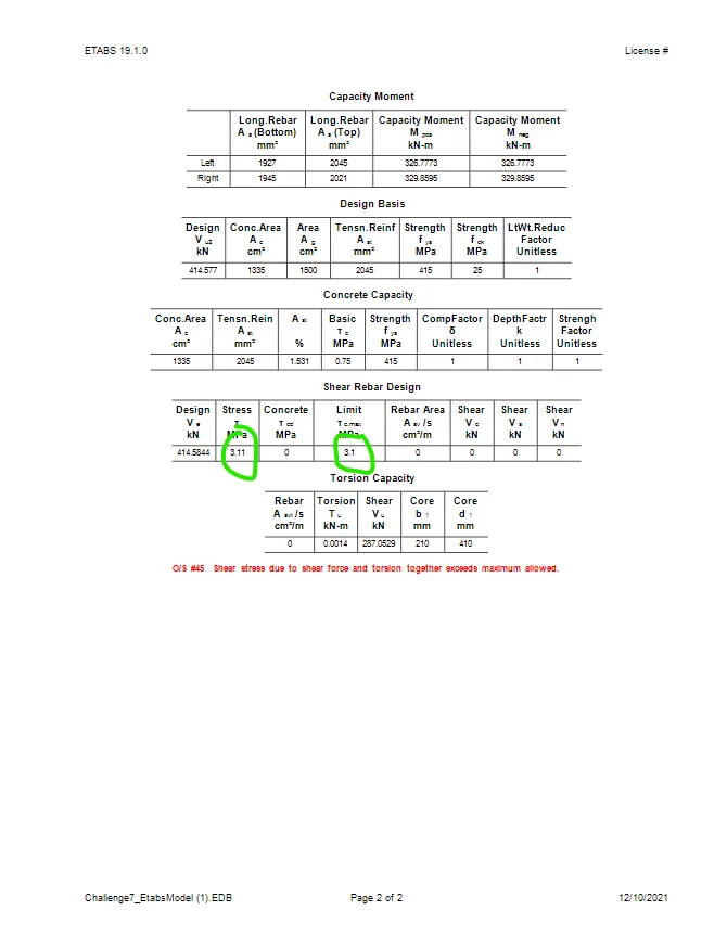
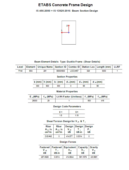
Reason of failure:-Here from the above shear details we can see that the limiting value of shear stress 3.1 MPa and the devoloped shear stress is 3.11 Mpa which is clearly shows that the it exceeds the limiting value of shear of the beam.
Possibilities for resolving:-
- Using higher grade of concrete
- reducing effective depth.
- By providing diagonal reinforcement bars.
C.Calculate value of the maximum shear force in any one of the spans in both the continuous beams, as per clause 6.3.3 (b) in IS 13920 – 2016. Also, confirm these values from shear force demand calculated by ETABS.Please note that if longitudinal reinforcement provided is more than required (as per ETABS results), the shear force demand will vary from what is provided by ETABS.
Grid A(Beam )
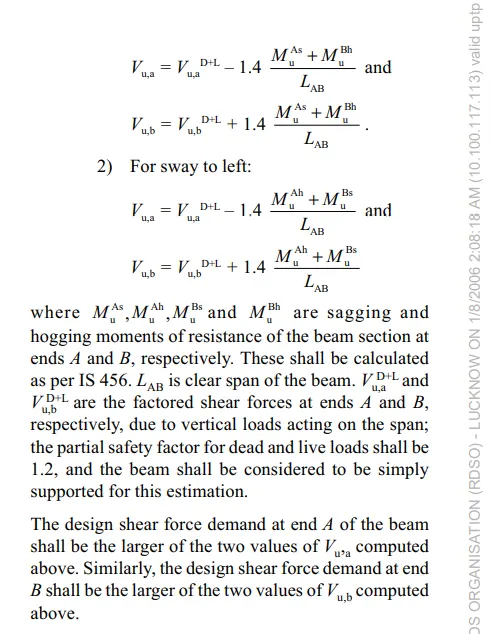
1.Sway to right
Mu(Sagging )= 164.52 KN-m
Mu(Hogging )= 293.53 KN-m
2.Sway to left=
Mu(Sagging )= 177.83 KN-m
Mu(Hogging )= 296.42 KN-m
Factored shear force Vu(D+L)= 39.2802 kN
Clear span, LAB= 5.375-(2*0.65/)= 4.725m
Now according to IS 13920
Vub= 174.99 KN (right sway)
Similarly left sway also computed.
Vub= 179.799 KN (Left sway)