Creating a Floor plan, Footing detail and Isometric view using AutoCad
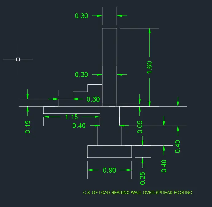
Drawing C1 :- Cross section of load bearing walls over spred footing
1.AIM:- To draw cross section of load bearing walls over spred footing
2.INTRODUCTION:- The cross section of load bearing wall over spread footing using AutoCAD is created by Lines and Rectangles.
3.PROCEDURE:
STEP 1:
- Open the AutoCAD software and click on new for a new drawing sheet.
- Enter UNITS in command box.
- Select DECIMAL in TYPE, 0.00 in PRECISION and METERS in UNITS TO SCALE INSERTED CONTENT. Press OK.
- Switch on ORTHOMODE.(f8) type PL in the command box.(polyline)
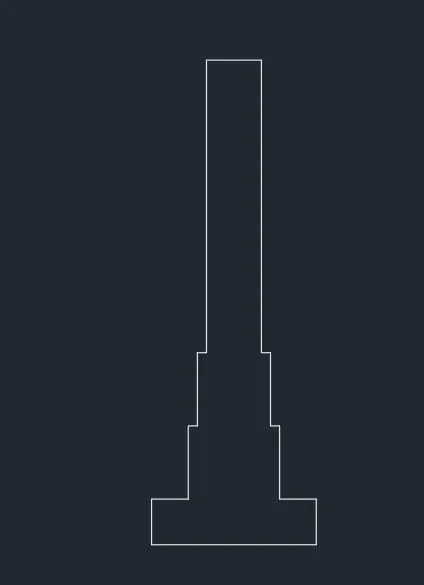
- from a random point of the drawing sheet draw polyline with a length of 0.9.
- then drag the mouse upwards and type 0.25 as length of polyline(ortho mode gives perfect 90 degree angle)
- Similarly type the corresponding length of lines such as
- 0.20 towards left
- 0.4 upwards
- 0.05 towards left
- 0.4 upwards
- 0.05 towards left
- 1.6 upwards
- 0.3 towards left
- 1.6 downwards
- 0.05 towards left
- 0.4 downwards
- 0.05 towards left
- 0.4 downwards
- 0.20 towards left
- 0.25 downwards
the above commands gives the following figure
STEP 2:
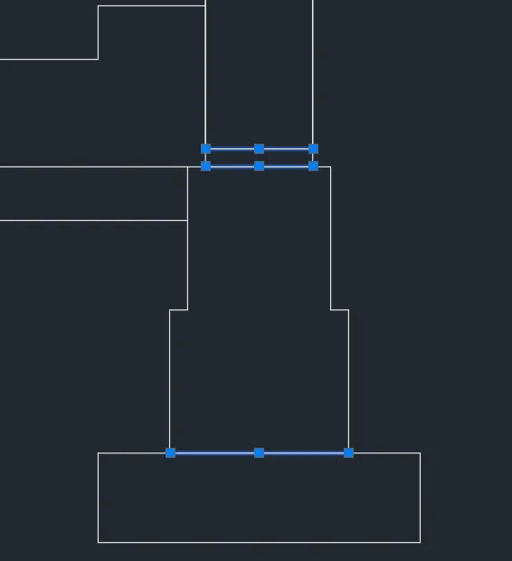
type L for line command and join the following selected lines in the figure.(ortho mde and object snap make this process easier.)
STEP 3
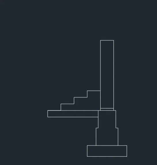
- Again PL for polyline command.
- Then drag the mouse pointer to the top left end of foundation block work at the ground level.
- Then draw 1.15 towards left , then 0.15 downwards and finally 1.15 towards right.
- press esc key
- Again PL for polyline command
- Then drag the mouse pointer to the top left corner of the rectangle drawn.
- then type the corresponding length of lines such as
- 0.3 towards right
- 0.15 upwards
- 0.3 towards right
- 0.15 upwards
- Repeat the above steps 3 more times.,then the steps are also finished.
the above commands gives the following figure
STEP 5:
- Enter DIMS in the command box.
- Click Modify
- Click SYMBOLS AND ARROWS. Enter 0.05 in Arrow size.
- Click TEXT. Enter 0.05 in Text height.
- Click OK.
- Select STANDARD in Style. Click SET CURRENT. Click close.
- Enter DIM in command box.
- Click the first point and second point of the object. Drag it to the desired location. The dimension will be fixed in the preferred location in the workspace.
- Drag the dimension ofall the objects in the workspace which are located in the given diagram.
RESULT:
CS of load bearing wall over spread footing is created by Lines and Rectangles using AutoCAD. The step-by-step procedure for creating crosssection of load bearing wall over spread footing is also explained, The Dimension and heading are also entered in the diagram.
Drawing C2 :- Cross section of isolated footing
1.AIM:- To draw cross section of isolated footing.
2.INTRODUCTION:- The cross section of isolated footing using AutoCAD is created by Lines and Rectangles.
3.PROCEDURE:
STEP 1:
- Open the AutoCAD software and click on new for a new drawing sheet.
- Enter UNITS in command box.
- Select DECIMAL in TYPE, 0.00 in PRECISION and METERS in UNITS TO SCALE INSERTED CONTENT. Press OK.
- Switch on ORTHOMODE.(f8)
- type PL for polyline.
- from a random point of the drawing sheet draw polyline with a length of 1.
- then drag the mouse upwards and type 0.4 as length of polyline(ortho mode gives perfect 90 degree angle)
- Similarly type the corresponding length of lines such as
- 0.38 towards left
- 1.6 upwards
- 0.24 towards left
- 1.6 downwards
- 0.05 towards left
- 1.6 upwards
- 0.38towards left
- 0.4 downwards.
the above commands gives the following figure
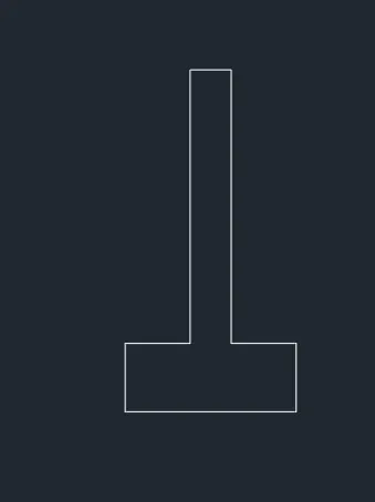
STEP 2:
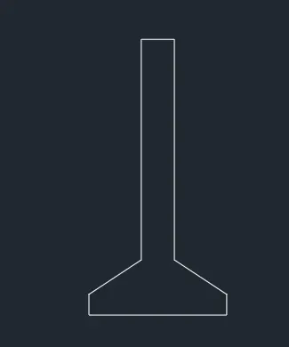
- Type CHAMFER command and press enter.
- type D in the command bar in the and assign the first distance as 0.38 and the second distance as 0.25
- Then click on top horizontal and vertical sides of the footing.
the above commands gives the following figure
Step 3
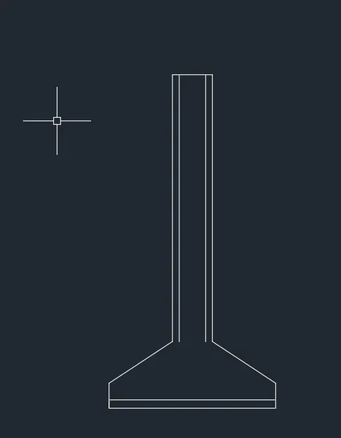
- type O for taking offset of column walls and bottom layer of footing.
- assign offset distance as 0.04.
- click on the lines on which offset needs to be taken.
the above commands gives the following figure
Step 4
- Type Extend for extending and joining the offset lines drawn just before.
- also trim the unwanted portion of the joined lines.
the above commands gives the following figure
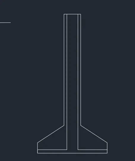
Step 5
- provide 0.05 bending on the both ends of bottom bars of footing.
- also offset at a distance of 0.5 vertical column stirrups.
the above commands gives the following figure
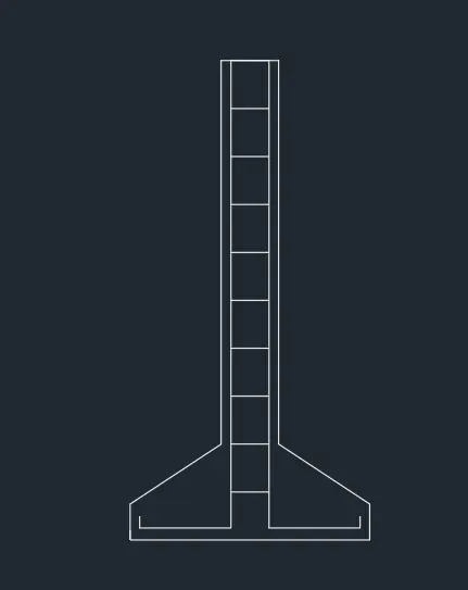
step 6
- Enter DIMS in the command box.
- Click Modify
- Click SYMBOLS AND ARROWS. Enter 0.05 in Arrow size.
- Click TEXT. Enter 0.05 in Text height.
- Click OK.
- Select STANDARD in Style. Click SET CURRENT. Click close.
- Enter DIM in command box.
- Click the first point and second point of the object. Drag it to the desired location. The dimension will be fixed in the preferred location in the workspace.
- Drag the dimension ofall the objects in the workspace which are located in the given diagram.
RESULT:
CS of isolated footing is created by Lines and Rectangles using AutoCAD. The step-by-step procedure for creating crosssection of load bearing wall over spread footing is also explained, The Dimension and heading are also entered in the diagram.
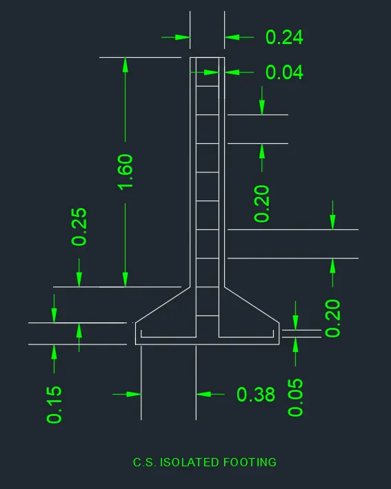
Drawing C3 :-CROSS-SECTION OF LINE DIAGRAM OF A TWO ROOM BUILDING
AIM : TO DRAW THE FIGURE C3 OF CROSS-SECTION OF LINE DIAGRAM OF A TWO ROOM BUILDING
INTRODUCTION : Line drawings are drawing with details of dimensions and components of building. Two room building consists of 1 x bedroom, 1 x living room and steps in both directions.
PROCEDURE :
STEP 1
POLYLINE Command: PL Enter
Specify start point: 0,0 Enter
Current line-width is 0.0000
Specify next point or [Arc/Halfwidth/Length/Undo/Width]: 3.6,0 Enter
Specify next point or [Arc/Close/Halfwidth/Length/Undo/Width]: 3.60,0 Enter
Specify next point or [Arc/Close/Halfwidth/Length/Undo/Width]: 3.6,-0.9 Enter
Specify next point or [Arc/Close/Halfwidth/Length/Undo/Width]: 4.60,-0.9 Enter
Specify next point or [Arc/Close/Halfwidth/Length/Undo/Width]: 4.6,0 Enter
Specify next point or [Arc/Close/Halfwidth/Length/Undo/Width]: 8.8,0 Enter
Specify next point or [Arc/Close/Halfwidth/Length/Undo/Width]: 8.8,3.6 Enter
Specify next point or [Arc/Close/Halfwidth/Length/Undo/Width]: 4.60,3.6 Enter
Specify next point or [Arc/Close/Halfwidth/Length/Undo/Width]: 4.6,4.5 Enter
Specify next point or [Arc/Close/Halfwidth/Length/Undo/Width]: 3.6,4.5 Enter
Specify next point or [Arc/Close/Halfwidth/Length/Undo/Width): 3.6,3.6 Enter
Specify next point or [Arc/Close/Halfwidth/Length/Undo/Width]: 0,3.6 Enter
Specify next point or [Arc/Close/Halfwidth/Length/Undo/Width]: C Enter
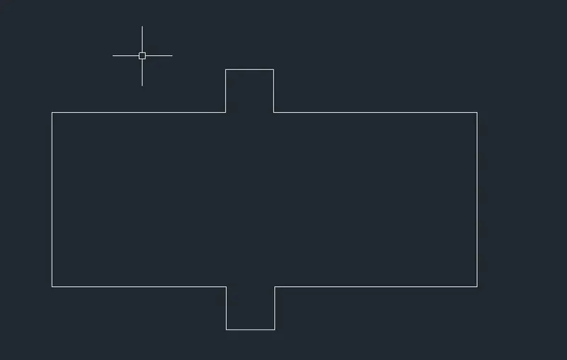
STEP 2
POLYLINE Command: PL Enter
Specify start point: 3.6,0 Enter
Current line-width is 0.0000
Specify next point or [Arc/Halfwidth/Length/Undo/Width]: 3.6,0.9 Enter
Specify next point or [Arc/Close/Halfwidth/Length/Undo/Width]: Esc / Enter
POLYLINE Command: PL Enter
Specify start point: 3.6,1.8 Enter
Current line-width is 0.0000
Specify next point or [Arc/Halfwidth/Length/Undo/Width]: 3.6,3.6 Enter
Specify next point or [Arc/Close/Halfwidth/Length/Undo/Width]: Esc / Enter
STEP 3
OFFSET Command: O Enter
Current settings: Erase source=No Layer=Source OFFSETGAPTYPE=0
Specify offset distance or [Through/Erase/Layer] : 0.3 Enter
Select object to offset or [Exit/Undo] :
Specify point on side to offset or [Exit/Multiple/Undo] :
Select object to offset or [Exit/Undo] :
Select object to offset or [Exit/Undo] <Exit»:
Specify point on side to offset or [Exit/Multiple/Undo] :
Select object to offset or [Exit/Undo] : *Cancel*
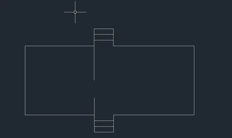
STEP 4
- MTEXT Command
- T Enter Current text style
- "Standard" Text height 2.5 Annotative
- No Specify first corner
- Specify opposite corner or [Height/Justify/Line spacing/Rotation/Style/Width/Columns]:
- COPY Command: CO Enter Select objects:1 found Select objects
- Current settings: Copy mode = Multiple Specify base point or [Displacement/mOde]
- Specify second point or [Array]
- Specify second point or [Array/Exit/Undo] <Exit': E Enter
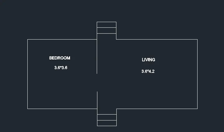
step 6
- Enter DIMS in the command box.
- Click Modify
- Click SYMBOLS AND ARROWS. Enter 0.05 in Arrow size.
- Click TEXT. Enter 0.05 in Text height.
- Click OK.
- Select STANDARD in Style. Click SET CURRENT. Click close.
- Enter DIM in command box.
- Click the first point and second point of the object. Drag it to the desired location. The dimension will be fixed in the preferred location in the workspace.
- Drag the dimension ofall the objects in the workspace which are located in the given diagram.
4.RESULT:
CS of isolated footing is created by Lines and Rectangles using AutoCAD. The step-by-step procedure for creating crosssection of CROSS-SECTION OF LINE DIAGRAM OF A TWO ROOM BUILDING is also explained, The Dimension and heading are also entered in the diagram.
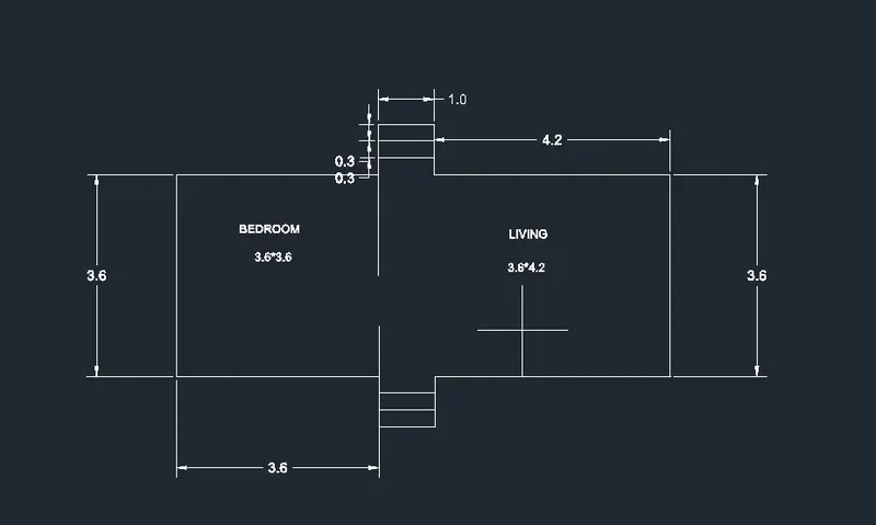
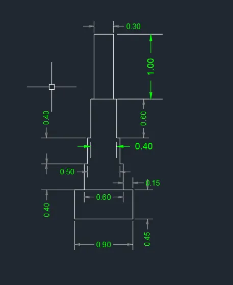
Drawing C4 :-Cross section of load bearing walls Showing foundation details.
1.AIM : TO DRAW THE FIGURE C3 OF CROSS-SECTION OF LINE DIAGRAM OF A TWO ROOM BUILDING
2.INTRODUCTION:- The cross section of load bearing wall showing foundation using AutoCAD is created by Lines and Rectangles.
3.PROCEDURE
STEP 1.
- Open the AutoCAD software and click on new for a new drawing sheet.
- Enter UNITS in command box.
- Select DECIMAL in TYPE, 0.00 in PRECISION and METERS in UNITS TO SCALE INSERTED CONTENT. Press OK.
- Switch on ORTHOMODE.(f8) type PL in the command box.(polyline)
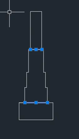
- from a random point of the drawing sheet draw polyline with a length of 0.9.
- then drag the mouse upwards and type 0.45 as length of polyline(ortho mode gives perfect 90 degree angle)
- Similarly type the corresponding length of lines such as
-
- 0.15 towards left
- 0.4 upwards
- 0.05 towards left
- 0.30 upwards
- 0.05 towards left
- 0.6 upwards
- 0.05 towards left
- 1.0 Upwards
- 0.3 towards left
- 1.0 downwards
- 0.05 towards left
- 0.6 downwards
- 0.05 towards left
- 0.3 downwards
- 0.05 towards left
- 0.4 downwards
- 0.15 towards left
- 0.45 downwards
the above commands gives the following figure
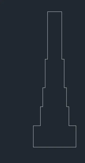
Step 2
- L command in the command box
- then join the top layer of footing and bottom layer of column.
4.Results.
CS of load bearing wall showing foundation is created by Lines and Rectangles using AutoCAD. The step-by-step procedure for creating crosssection of load bearing wall over spread footing is also explained, The Dimension and heading are also entered in the diagram.
Drawing - C5 ISOMETRIC VIEW OF STEPS
1.AIM: To create isometric view of steps using AutoCAD.
2.INTRODUCTION: Isometric view of steps using AutoCAD is created by Lines. The procedure and result should be written after creating the isometric view of steps.
3.PROCEDURE
STEP 1
- Open the AutoCAD software and click start Drawing tab.
- Enter UNITS in command box.
- Select DECIMAL in TYPE, 0.00 in PRECISION and METERS in UNITS TO SCALE INSERTED CONTENT. Press 0K.
- Type DS in command box
- Put snap off and grid off. Click isometric snap on.
- Switch on ORTHOMODE.
- Click Isometric left in the status bar.
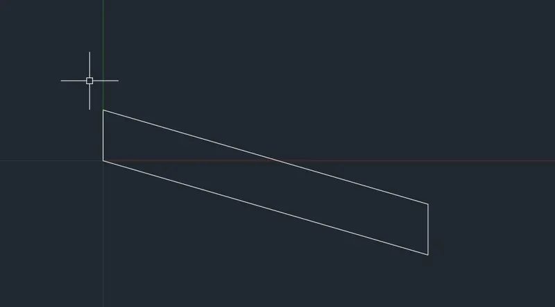
- Enter L in command box.
- Enter 0,0 as first point in command box.
- Place the cursor upwards and enter 0.15 as next point in command box.
- Place the cursor right side and enter 1.00 as next point in command box.
- Place the cursor downwards and enter 0.15 as next point in command box.
- Place the cursor left side and enter 1.00 as next point in command box.
- Press ENTER or click CLOSE in command box.
STEP 2
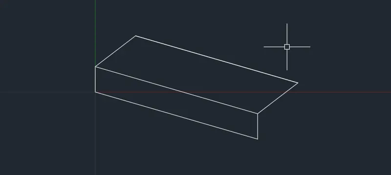
- Click Isometric right in the status bar.
- Enter L in command box.
- Click on upper top corner of the diagram.
- Enter 0.30 as first point in command box.
- Enter CO in command box which is COPY.
- Select the line of 0.30 length.
- Press ENTER.
- Click the Basepoint as upper top corner.
- Click it at 1.00 distance at other point.
- Enter CO in command box.
- Select the line of 0.30 length at lower top corner of the diagram.
- Click it at 0.15 distance at lower point.
- Press ENTER.
STEP 3:
- Enter CO in command box.
- Select the rectangular box.
- Press ENTER
- Click the baseline as lower corner of the rectangle.
- Click it after the two straight lines and fix it.
STEP 4
- Enter CO in command box.
- Select the two straight lines opposite to each other.
- Press ENTER.
- Click the top corner of the rectangle as basepoint.
- Fix the two lines after the second rectangular box.
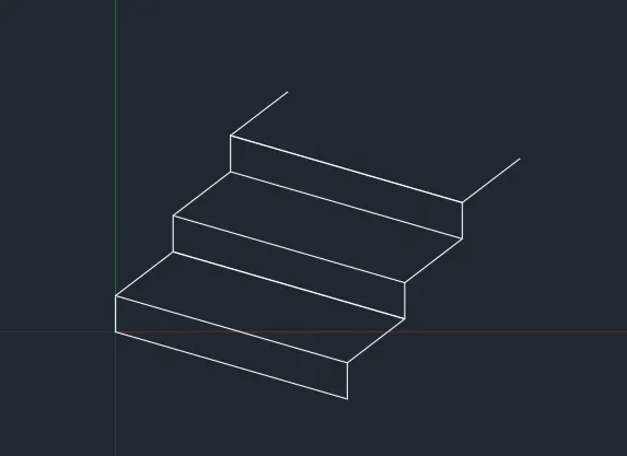
STEP 5
- Enter CO in command box.
- Again, copy the rectangular box and two opposite straight lines.
- Fix 3 rectangular boxes and 6 lines
STEP 6
- Enter CO in command box.
- Select the upper line in the last rectangular box.
- Click the last rectangle's top corner point.
- Fix it after two opposite lines.
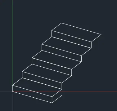
STEP 7
- Enter CO in command line.
- Select the right side 0.30 dimension line.
- Click the lower top corner of rectangle as basepoint.
- Fix it below at a distance of 0.15.
- Switch off ORTHOMODE.
- Enter L in command box.
- Connect the two unconnected lines.
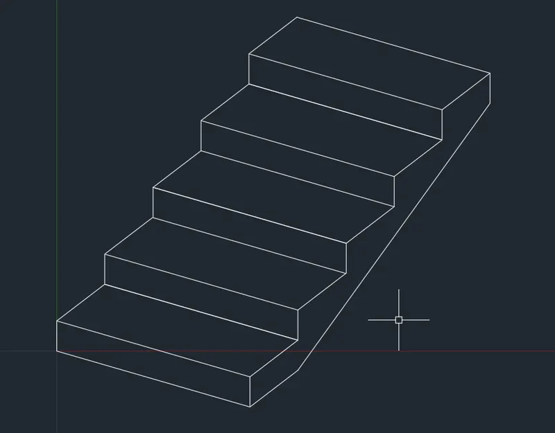
STEP 8
- Enter DIMS in the command box.
- Click Modify.
- Click SYMBOLS AND ARROWS.
- Enter 0.05 in Arrow size.
- Click TEXT. Enter 0.05 in Text height.
- Click OK.
- Select STANDARD in Style.
- Click SET CURRENT.
- Click close.
- Enter DIM in command box.
- Click the first point and second point of the object.
- Drag it to the desired location.
- The dimension will be fixed in the preferred location in the workspace.
- Drag the dimension of all the objects in the workspace which are located in the given diagram.
- Enter TEXT in command box.
- Enter 0.1 as text height.
- Enter O as text rotation angle in command box.
- Press ENTER.
- Enter the text given in the diagram in the workspace.
- Press ENTER
4.RESULT
Isometric view of steps is created by Lines using AutoCAD. The step-by-step procedure for creating the Isometric view of steps is also explained. The Dimension and heading are also entered in the diagram.
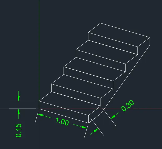
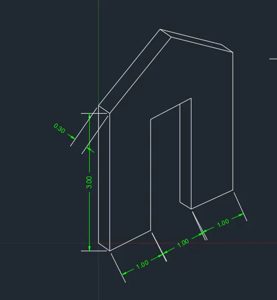
Drawing - C6 ISOMETRIC VIEW OF GABLE WALLS
1.AIM: To create isometric view of Gable walls using AutoCAD.
2.INTRODUCTION: Isometric view of steps using AutoCAD is created by Lines. The procedure and result should be written after creating the isometric view of Gable walls.
3.PROCEDURE:
STEP 1
- Open the AutoCAD software and click start Drawing tab.
- Enter UNITS in command box.
- Select DECIMAL in TYPE, 0.00 in PRECISION and METERS in UNITS TO SCALE INSERTED CONTENT. Press 0K.
- Type DS in command box
- Put snap off and grid off. Click isometric snap on.
- Turn on the Isometric Drafting.
- Select Isoplane Left
- Select the Line tool by entering 'LINE' command in the command tab.
- Keep the Ortho mode ON.
- Specify the first point as 0,0 in the command line.
- Specify the next point as 3.00, pointing the cursor towards the upward direction.
- Specify the next point as 0.30, pointing the cursor towards the left direction.
- Specify the next point as 3.00, pointing the cursor towards the downward direction.
- Click "Close' on the command line.
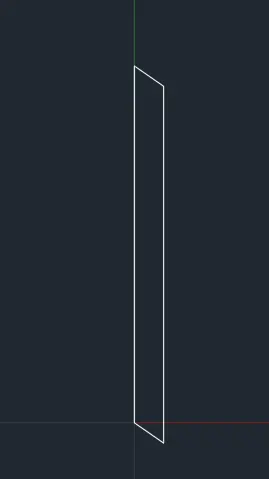
STEP 2
• Select Isoplane Right from Isometric drafting dropdown list.
• Select the Line tool by entering 'LINE' command in the command tab.
• Keep the Ortho mode ON.
• Specify the first point as top right corner of the above object.
• Specify the next point as 3.00, pointing the cursor towards the right direction.
• Specify the next point as 3.00, pointing the cursor towards the downward direction.
• Specify the next point as 1.00, pointing the cursor towards the left direction.
• Specify the next point as 2.42, pointing the cursor towards the upward direction.
• Specify the next point as 1.00, pointing the cursor towards the left direction.
•Specify the next point as 2.42, pointing the cursor towards the downward direction.
•Specify the next point as 1.00 pointing the cursor towards the left direction.
• Press 'Esc' to cancel the LINE command.
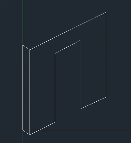
STEP 3
- Select Isoplane left from Isometric drafting dropdown list.
- Keep the Ortho mode ON.
- Select the Line tool by entering 'LINE' command in the command tab.
- Specify the first point at the corner of the door opening.
- Specify the next point as 0.30, pointing the cursor towards the left direction.
- Specify the next point as 2.12, pointing the cursor towards the upward direction.
- Press 'Esc' to cancel the LINE command.
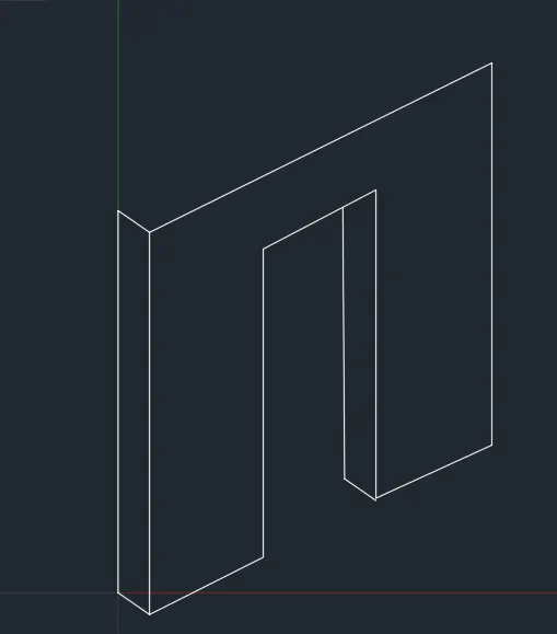
STEP 4
- Select Isoplane right from Isometric drafting dropdown list.
- Keep the Ortho mode ON.
- Select the Line tool by entering ‘LINE' command in the command tab.
- Specify the first point at the midpoint of the top line.
- Specify the next point as 1.00, pointing the cursor towards the upward direction.
- Draw line to join the top to the top left corner of the wall
- Press 'Esc' to cancel the LINE command.
- Select the Line tool again by entering 'LINE' command in the command tab, and join the top to the other corner of the wall.
- Press 'Esc' to cancel the LINE command.
- Delete the extra lines.
STEP 5
- Select the Copy tool by entering 'CO' command in the command tab.
- Select the both the lines of the mount.
- Specify the basepoint as the top left corner of the wall.
- Copy the lines of the mount to the adjacent top left corner of the wall.
- Press 'Esc' to cancel the COPY command.
- Select the Line tool by entering 'LINE' command in the command tab.
- Join the midpoint of the front face of the mount to the midpoint of the back face of the mount.
- Press 'Esc' to cancel the LINE command.
- Select the Line tool again by entering 'LINE' command in the command tab.
- Join the remaining top right corners of the wall.
- Press 'Esc' to cancel the LINE command.
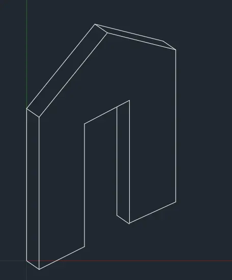
STEP 6
- Enter DIMS in the command box.
- Click Modify.
- Click SYMBOLS AND ARROWS.
- Enter 0.05 in Arrow size.
- Click TEXT. Enter 0.05 in Text height.
- Click OK.
- Select STANDARD in Style.
- Click SET CURRENT.
- Click close.
- Enter DIM in command box.
- Click the first point and second point of the object.
- Drag it to the desired location.
- The dimension will be fixed in the preferred location in the workspace.
- Drag the dimension of all the objects in the workspace which are located in the given diagram.
- Enter TEXT in command box.
- Enter 0.1 as text height.
- Enter O as text rotation angle in command box.
- Press ENTER.
- Enter the text given in the diagram in the workspace.
- Press ENTER
4.RESULT
Isometric view of Gable walls is created by Lines using AutoCAD. The step-by-step procedure for creating the Isometric view of Gable walls is also explained. The Dimension and heading are also entered in the diagram.