Creation of geometries by Coordinate system methods using AutoCad
Drawing P1
Aim:- Create the geometries from P1 using all the coordinates system methods.
Procedure:-
1. Using absolute coordinate system
Steps
- Open autocad software.
- open new drawing sheet using short key cntrl N or from the application tab.
- Assign the units .
- Using the commands draw the figure
- Commands used
- L command for line key
- assign the first coordinates as 2,1
- then press enter.
- type the next coordinates such as
(8,1),(8,2),(3,2),(3,6),(8,6),(8,7),(2,7).(press enter key after typing each coordinates)
e.Finally click on close tab in the command bar to enclose the figure.(or type 2,1)
Result.
Final result after foolowing the above steps

2. Using Relative rectangular coordinate system
Steps
- Open autocad software.
- open new drawing sheet using short key cntrl N or from the application tab.
- Assign the units .
- Using the commands draw the figure.
-
Commands used
- L command for line key
- assign the first coordinates as ( 2,1) in the command bar
- then press enter.
- type the next relative coordinates such as
(@6,0),(@0,1),(@-5,0),(@3,2),(@0,4),(@5,0),(@0,1),(@-6,0).(press enter key after typing each coordinates)
e.Finally click on close tab in the command bar to enclose the figure.( or type (@0,-6)
Result.
Final result after foolowing the above steps
3. Using Relative polar coordinate system
Steps
- Open autocad software.
- open new drawing sheet using short key cntrl N or from the application tab.
- Assign the units .
- Using the commands draw the figure.
-
Commands used
- L command for line key
- assign the first coordinates as ( 2,1) in the command bar
- then press enter.
- type the next relative coordinates such as.
(@6<0),(@1<90), (@5<180), (@4<90),( @5<0),( @1<90),( @6<180)
e.Finally click on close tab in the command bar to enclose the figure.( or type (@6<180))
Result.
Final result after following the above steps
4.Direct distance entry
Steps
- Open autocad software.
- open new drawing sheet using short key cntrl N or from the application tab.
- Assign the units .
- Using the commands draw the figure.
-
Commands used
- L command for line key
- assign the first coordinates as ( 2,1) in the command bar
- click mouse on right side for fixing the direction of line.
- type 6 as lenght of the line in the command bar.
- Press enter key
- click mouse in the upward direction
- type the next lengths as "1"+ enter key
- click mouse in the left direction
- type the next lengths as "5"+ enter key
- click mouse in the upward direction
- type the next lengths as "4"+ enter key
- click mouse in the right direction
- type the next lengths as "5"+ enter key
- click mouse in the upward direction
- type the next lengths as "1"+ enter key
- click mouse in the left direction
- type the next lengths as "6"+ enter key
- click mouse in the downward direction
- type the next lengths as "6"+ enter key.
Result.
Final result after following the above steps
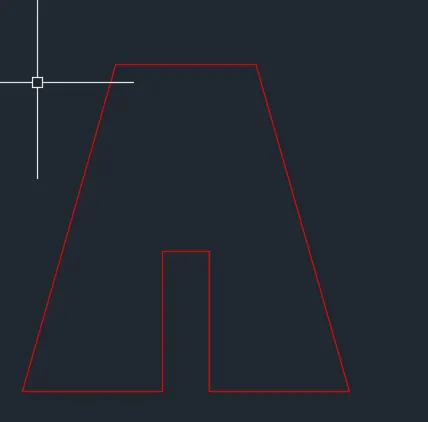
Drawing P2
Aim:- Create the geometries from P2 using all the coordinates system methods.
Procedure:-
1. Using absolute coordinate system
Steps
- Open autocad software.
- open new drawing sheet using short key cntrl N or from the application tab.
- Assign the units .
- Using the commands draw the figure
- Commands used
- L command for line key
- assign the first coordinates as 2,1
- then press enter.
- type the next coordinates such as
(5,1),(5,4),(6,4),(6,1),(9,1),(7,8),(4,8).(press enter key after typing each coordinates)
e.Finally click on close tab in the command bar to enclose the figure.(or type 2,1)
Result.
Final result after following the above steps

2. Using Relative rectangular coordinate system
Steps
- Open autocad software.
- open new drawing sheet using short key cntrl N or from the application tab.
- Assign the units .
- Using the commands draw the figure.
-
Commands used
- L command for line key
- assign the first coordinates as ( 2,1) in the command bar
- then press enter.
- type the next relative coordinates such as
(@3,0),(@0,4),(@1,0),(@0,-4),(@3,0),(@-2,7),(@-3,0).(press enter key after typing each coordinates)
e.Finally click on close tab in the command bar to enclose the figure.( or type (@-2,-7)
Result.
Final result after following the above steps
3. Using Relative polar coordinate system
Steps
- Open autocad software.
- open new drawing sheet using short key cntrl N or from the application tab.
- Assign the units .
- Using the commands draw the figure.
-
Commands used
- L command for line key
- assign the first coordinates as ( 2,1) in the command bar
- then press enter.
- type the next relative coordinates such as.
(@3<0),(@4<90), (@1<0), (@4<270),( @3<0),( @7.28<105.95),( @3<180)
e.Finally click on close tab in the command bar to enclose the figure.( or type (@7.28<254.05))
Result.
Final result after following the above steps

4.Direct distance entry
Steps
- Open autocad software.
- open new drawing sheet using short key cntrl N or from the application tab.
- Assign the units .
- Using the commands draw the figure.
-
Commands used
- L command for line key
- assign the first coordinates as ( 2,1) in the command bar
- click mouse on right side for fixing the direction of line.
- type 3 as lenght of the line in the command bar.
- Press enter key
- click mouse in the upward direction
- type the next lengths as "4"+ enter key
- click mouse in the right direction
- type the next lengths as "1"+ enter key
- click mouse in the downward direction
- type the next lengths as "4"+ enter key
- click mouse in the right direction
- type the next lengths as "3"+ enter key
- click mouse in the upward direction
- type the <105.95 for the angle at that point.
- type the next lengths as "7.28"+ enter key
- click mouse in the left direction
- type the next lengths as "3"+ enter key
- click mouse in the downward direction
- type the <254.05 for the angle at that point.
- type the next lengths as "7.28"+ enter key.
Result.
Final result after following the above steps
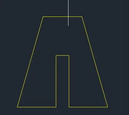
Drawing P4
Aim:- Create the geometries from P4 using any of the coordinates system methods.
Procedure:-
Using Relative rectangular coordinate system
Steps
- Open autocad software.
- open new drawing sheet using short key cntrl N or from the application tab.
- Assign the units .
- Using the commands draw the figure.
-
Commands used
- L command for line key
- assign the first coordinates as ( 2,1) in the command bar
- then press enter.
- type the next relative coordinates such as:
(@1,0),(@0,4),(@2,-2),(@2,2),(@0,-4),(@1,0),(@0,7),(@-1,0),(@-2,-3),(@-1,0),.(press enter key after typing each coordinates)
e.Finally click on close tab in the command bar to enclose the figure.( or type (@0,-7)
Result.
Final result after following the above steps.
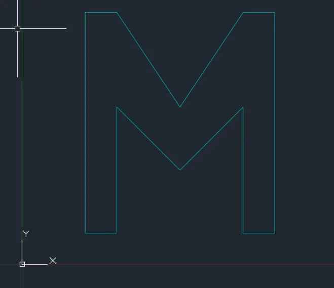
Drawing P5
Aim:- Create the geometries from P5 using any of the coordinates system methods.
Procedure:-
Using Relative rectangular coordinate system
Steps
- Open autocad software.
- open new drawing sheet using short key cntrl N or from the application tab.
- Assign the units .
- Using the commands draw the figure.
-
Commands used
- L command for line key
- assign the first coordinates as ( 2,1) in the command bar
- then press enter.
- type the next relative coordinates such as:
(@0,8),(@7,0),(@0,-8),(@-4,0),(@0,1),(@3,0),(@0,6),(@-5,0),(@0,-7),,.(press enter key after typing each coordinates)
e.Finally click on close tab in the command bar to enclose the figure.( or type (@-1,0)
Result.
Final result after following the above steps.
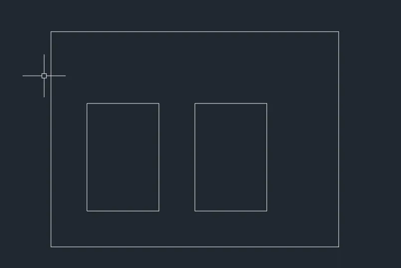
Drawing P7
Aim:- Create the geometries from P7 using any of the coordinates system methods.
Procedure:-
Using Relative rectangular coordinate system
Steps
- Open autocad software.
- open new drawing sheet using short key cntrl N or from the application tab.
- Assign the units .
- Using the commands draw the figure.
-
Commands used
- L command for line key
- assign the first coordinates as ( 2,1) in the command bar
- then press enter.
- type the next relative coordinates such as:
(@8,0),(@0,6),(@-8,0),),,,.(press enter key after typing each coordinates)
e.click on close tab in the command bar to enclose the figure.( or type (@0,-6)
f.L command for line key
g.assign the next coordinates as ( 3,2) in the command bar
h.then press enter.
i. type the next relative coordinates such as:
(@2,0),(@0,3),(@-2,0),),,,.(press enter key after typing each coordinates)
j. click on close tab in the command bar to enclose the figure.( or type (@0,-3)
k. L command for line key
l. assign the next coordinates as ( 6,2) in the command bar
m. then press enter.
i. type the next relative coordinates such as:
(@2,0),(@0,3),(@-2,0),),,,.(press enter key after typing each coordinates)
j.finally click on close tab in the command bar to enclose the figure.( or type (@0,-3)
Result.
Final result after following the above steps.
Drawing P8
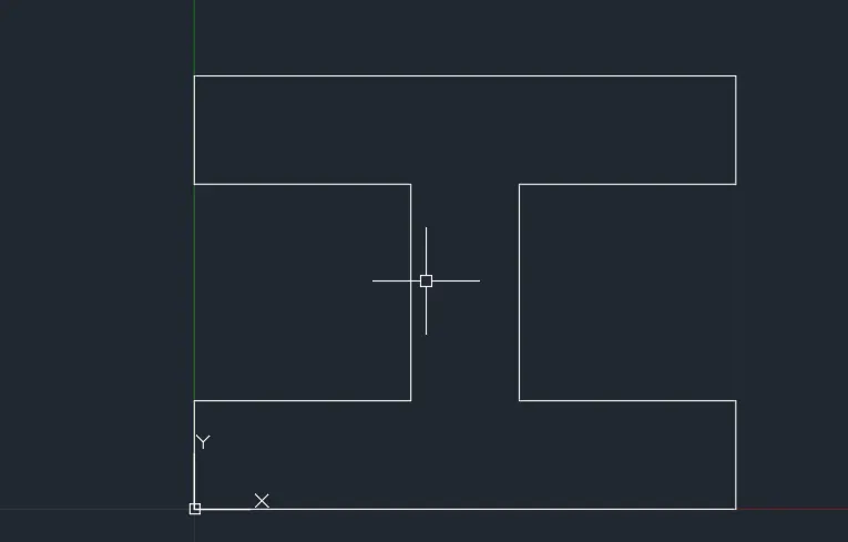
Aim:- Create the geometries from P8 using any of the coordinates system methods.
Procedure:-
Using Relative rectangular coordinate system
Steps
- Open autocad software.
- open new drawing sheet using short key cntrl N or from the application tab.
- Assign the units .
- Using the commands draw the figure.
-
Commands used
- L command for line key
- assign the first coordinates as ( 0,0) in the command bar
- then press enter.
- type the next relative coordinates such as:
(@10,0),(@0,2),(@-4,0),(@0,4),(@4,0),(@0,2),(@-10,0),(@0,-2),(@4,0),(@0,-4),(@-4,0),.(press enter key after typing each coordinates)
e.finally click on close tab in the command bar to enclose the figure.( or type (@0,-2)
Result.
Final result after following the above steps.
Drawing P9
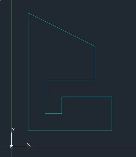
Aim:- Create the geometries from P9 using any of the coordinates system methods.
Procedure:-
Using Relative rectangular coordinate system
Steps
- Open autocad software.
- open new drawing sheet using short key cntrl N or from the application tab.
- Assign the units .
- Using the commands draw the figure.
-
Commands used
- L command for line key
- assign the first coordinates as ( 1,1) in the command bar
- then press enter.
- type the next relative coordinates such as:
(@5,0),(@0,2),(@-3,0),(@0,-1),(@-1,0),(@0,2),(@3,0),(@0,2),(@-4,2),.(press enter key after typing each coordinates)
e.finally click on close tab in the command bar to enclose the figure.( or type (@0,-7)
Result.
Final result after following the above steps.
Drawing P10
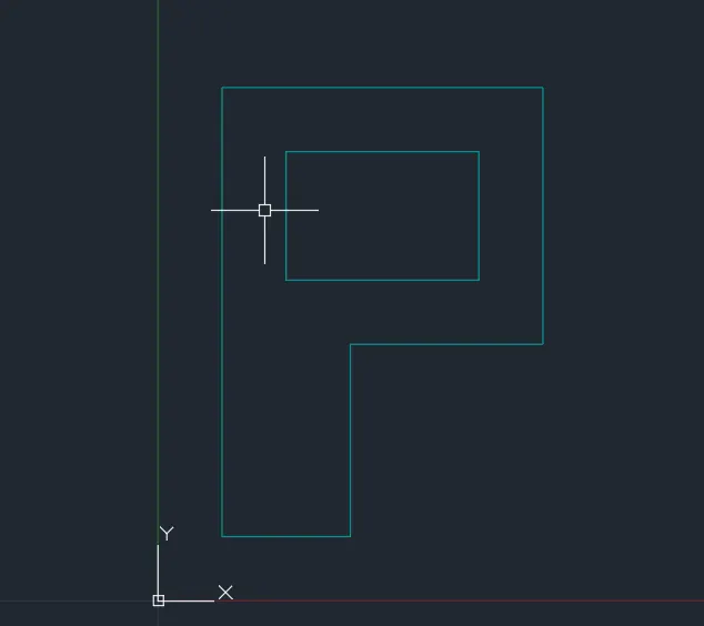
Aim:- Create the geometries from P10 using any of the coordinates system methods.
Procedure:-
Using Relative rectangular coordinate system
Steps
- Open autocad software.
- open new drawing sheet using short key cntrl N or from the application tab.
- Assign the units .
- Using the commands draw the figure.
-
Commands used
- L command for line key
- assign the first coordinates as ( 1,1) in the command bar
- then press enter.
- type the next relative coordinates such as:
(@2,0),(@0,3),(@3,0),(@0,4),(@-5,0).(press enter key after typing each coordinates)
e.click on close tab in the command bar to enclose the figure.( or type (@0,-7)
f.L command for line key
g.assign the first coordinates as ( 2,5) in the command bar
h.then press enter.
i.type the next relative coordinates such as:
(@3,0),(@0,2),(@-3,0)(press enter key after typing each coordinates)
j.click on close tab in the command bar to enclose the figure.( or type (@0,-2)
Result.
Final result after following the above steps.
Civil Related Drawings
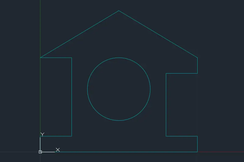
Drawing Profile wood
Aim:- Design the Drawing of Profile wood using any of the coordinates system methods.
Procedure:-
Using Relative rectangular coordinate system
Steps
- Open autocad software.
- open new drawing sheet using short key cntrl N or from the application tab.
- Assign the units .
- Using the commands draw the figure.
-
Commands used
- L command for line key
- assign the first coordinates as ( 0,0) in the command bar
- then press enter.
- type the next relative coordinates such as:
(@10,0),(@0,1),(@-2,0),(@0,4),(@2,0),(@0,1),(@-5,9),(@-5,-3),(@2,0),(@0,-5),(@-2,0),(@0,-1)(press enter key after typing each coordinates)
e.click on close tab in the command bar to enclose the figure.( or type (@0,-1)
f.C command for CIRCLE
g.assign the center coordinates as ( 5,4) in the command bar
h.then press enter.
i.enter radius of the circle as 2 in the command bar
j.then press enter.
Result.
Final result after following the above steps.
Queen Post Truss
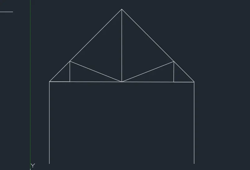
Aim:- Design the Drawing of Quenn Post Truss using any of the coordinates system methods.
Procedure:-
Using Relative polar coordinate system & direct distance entry
Steps
- Open autocad software.
- open new drawing sheet using short key cntrl N or from the application tab.
- Assign the units .
- Using the commands draw the figure.
-
Commands used
- L command for line key
- assign the first coordinates as ( 1,1) in the command bar
- then press enter.
- type the next relative coordinates such as:
(@4<90),(@5<45), (@5<315),(@4<270)
5. Now press escape.
6. L command for line key
7. assign thecoordinates as ( 1,4) in the command bar
8.then press enter.
9.type the next relative coordinates such as:
(@3.556<0),(@3.556<90)
10.Now press escape.
11. L command for line key
12. assign the first coordinates as ( 8,4) in the command bar
13.then press enter.
14.type the next relative coordinates such as:
(@1<180),(@1<90)(press enter key after typing each coordinates)
15. Now join (7,5) and (5.556,6)(press enter key after typing each coordinates)
16.similarly join (2,5) and (5.556,6).(press enter key after typing each coordinates)
17assign thecoordinates as ( 2,5) in the command bar
(@1<270),(@1<180).(press enter key after typing each coordinates)
Result.
Final result after following the above steps.
 .
.
Drawing monopost
Aim:- Design the Drawing of monopost Truss using any of the coordinates system methods.
Procedure:-
Using absolute coordinate system
Steps
- Open autocad software.
- open new drawing sheet using short key cntrl N or from the application tab.
- Assign the units .
- Using the commands draw the figure.
-
Commands used
- L command for line key
- assign the first coordinates as ( 1,1) in the command bar
- then press enter.
- type the next relative coordinates such as:
(7,1),(7,3), (1,1)(press enter key after typing each coordinates)
5. press escape key.
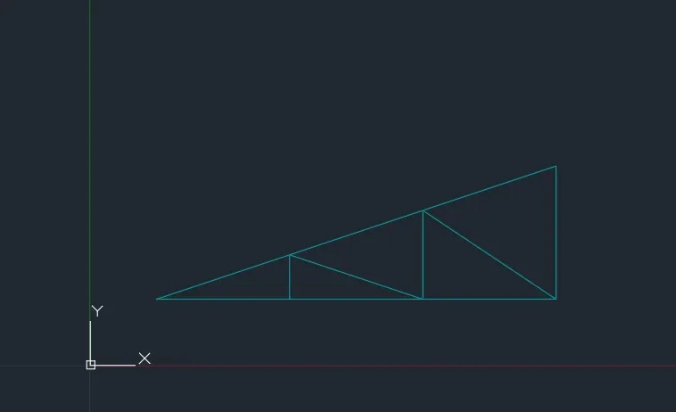
6.now enter L key
7. (7,1),(5,2.666),( 5,1),(3,1.667), (3,1), and finally (1,1)(press enter key after typing each coordinates)
8.
Result.
Final result after following the above steps.