Reinforcement Detailing of Beams from ETABS output
AIM: from given detailed design of concrete-1 G=4 buildig,follwoing need to be obtained.
- Provide details of longitudinal and shear reinforcement for the two continuous beams.
- Provide reasons for failure of the middle span along grid A.
- Calculate value of the maximum shear force in any one of the spans in both the continuous beams, as per clause 6.3.3 (b) in IS 13920 – 2016.
INTRODUCTION:
- Beam to be first member to detailed in seismic design,based on the analysis result(bending moment).
- The longituidinal reinforcement of beam and its associated moement resistance to be used for capacity design of column and beam/column joints so that they are stronger in flexural than the beams.
- while calculating logituindinal reinfocement axial force/torsion is neglected,only bending moment and shear force is considered.
- while designinng the reinforcement for longitunidal and shear,IS 13920 and IS 456 is considered.
PROCEDURE:
- once the designed column building is opened in ETABS,run the analyses.
- go to concrete frame option>start design/check.
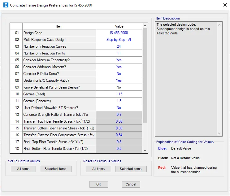
- concrete frame>view for design prefrence,recheck the design codes.
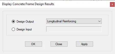
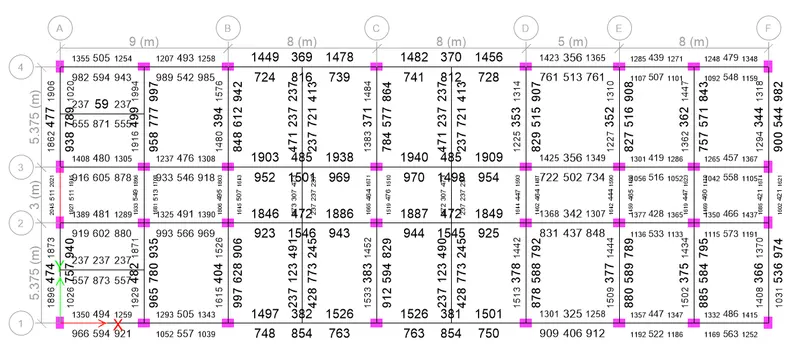
- concrete frame>display design info>longitudinal reinforcement(default setting).
1) Provide details of longitudinal and shear reinforcement for the two continuous beams.
- reinforcement detail to be provideed for grid A and 3,right click on any of the beam on the A gird.
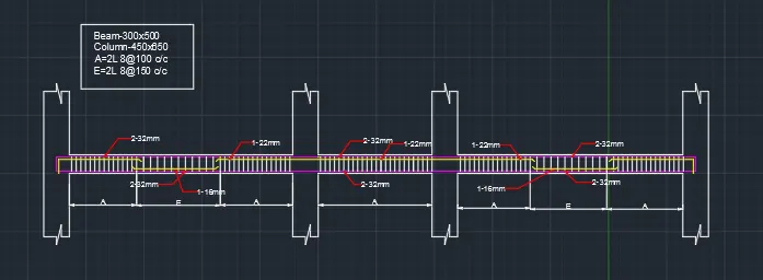
- in order to provide longitudinal and shear reinforcement,calculate Ast,number of bars and dia of bars based on code book.
For grid A-
at bottom,highest reinforcement area at support and center are 2045 and 477 mm^2.
lets provide 2 bars of 32mm and 1 bar of 22mm.
at top,highest reinforcement area at support and center are 1972 and 789 mm^2.
lets provide 2 bars of 32mm and 1 bar of 16mm.
For grid 3-
at bottom,highest reinforcement area at support and center are 520 and 375 mm^2.
lets provide 2 bars of 32mm dia and 1 bar of 16mm dia.
at top,highest reinforcement area at support and center are 816 and 320 mm^2.
lets provide 2 bars of 25mm and 1 bar of 16mm dia.
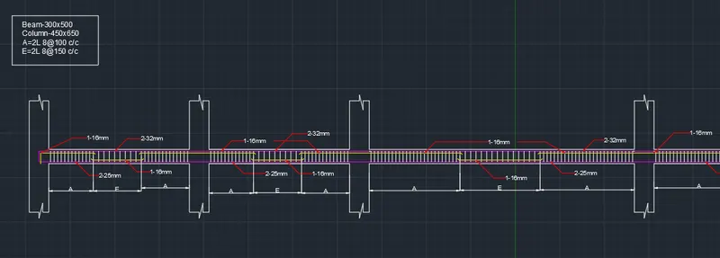
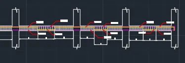
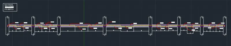
2) Provide reasons for failure of the middle span along grid A.
along grid A- their is unequal span length beams,which distrub the load distribution.Instead of equal transfer of loads their will be unequal distribution of load among three beams at grid A.In order to avoid the failure either span of all beams to be maintained same or provide additional shear links and longitudinal reinforcement at middle beam .
3)Calculate value of the maximum shear force in any one of the spans in both the continuous beams, as per clause 6.3.3 (b) in IS 13920 – 2016.
- select the beam and rgiht click,a new tab appears.
- select an combination and click on details,select shear details.
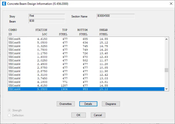
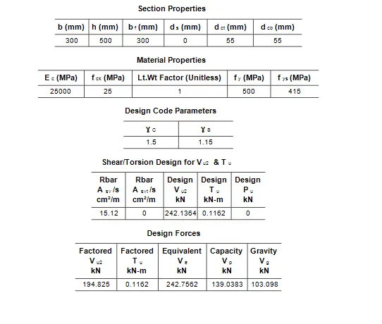
- from IS 13920 under clause 6.3.3 the design shear force of equivalent Ve=242.7 kN
- factored shear force for UDCons66 is 194.825 kN.
- designed shear force is greater than factored shear force,hence analysis is done correct.
RESULT-
- longitudinal and shear reinforcement for continuous beam of grid A and 3 is provided.
- reason for failure in middle span is known.
- desingn shear force is obtained from etabs analysis.