Reinforcement Detailing of Beams from ETABS output
aim
Detailed design of concrete buildings -1
Detail design of beams in Etabs 2018.
The ETABS file for a G+4 building is provided. Run the analysis and design the RCC Moment ResistingFrame. The following challenge deals specifically with two continuous beams in the 1st floor.
1) 3 span continuous beam along grid A
2) 7 span continuous beam along grid 3
Address the following issues thereafter.
• Provide details of longitudinal and shear reinforcement for the two continuous beams. Sketch the beam elevation details or draft it using autocad software. A sample of how beam elevation details is prepared in consultancy firms is provided below. Participants can prepare it as per their preference:
Provide reasons for failure of the middle span along grid A. What are the possible ways this issue can be resolved?
• Calculate value of the maximum shear force in any one of the spans in both the continuous beams, as per clause 6.3.3 (b) in IS 13920 – 2016. Also, confirm these values from shear force demand calculated by ETABS.Please note that if longitudinal reinforcement provided is more than required
preocedure
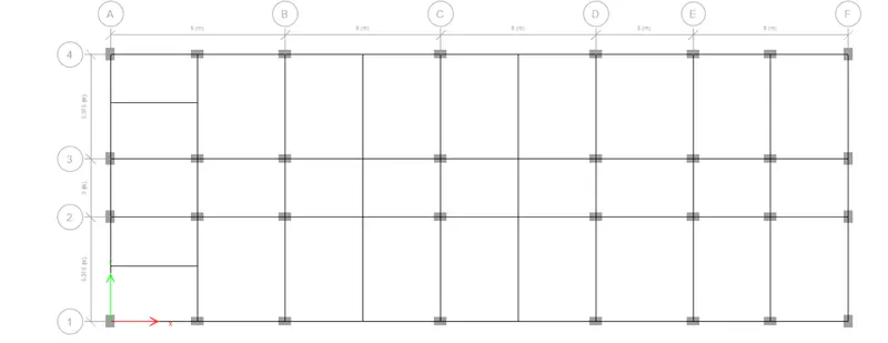
- We are going to review the supplied input.
- Input was already developed structural model of a G+4 building.
- So the supplied input was openend using the Etabs applicatio.
- And the model was reviewd.
- And as said the model was set to run the analysis.
- Thus run analysis is shown below
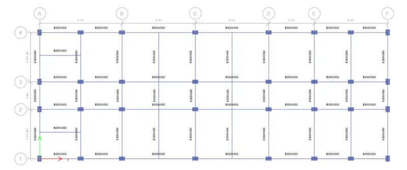
- in plan view select the first floor plan and apply it
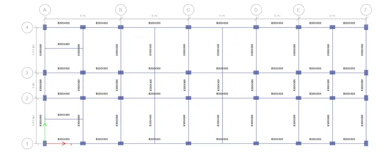
- select at grid 3 and click it
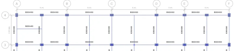
- next step and run analyse
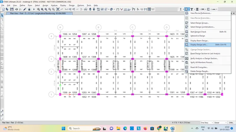
- select concrete frame design and click it
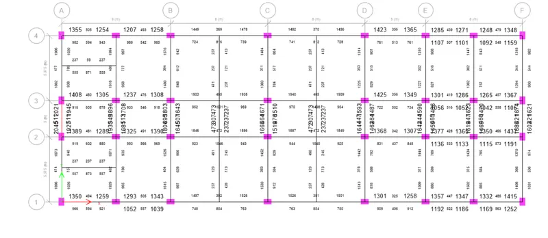
- select the display design info
-
- And as said in the question we have taken said beams in consideration.
- The considered beams are shown below
Longitudinal reinforcement of the beam for Grid A
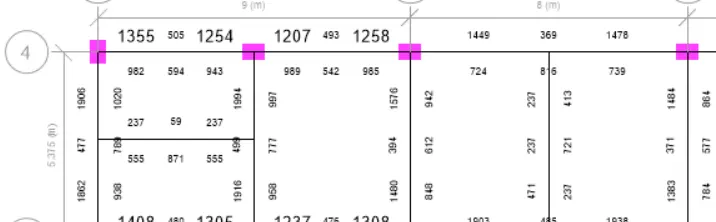
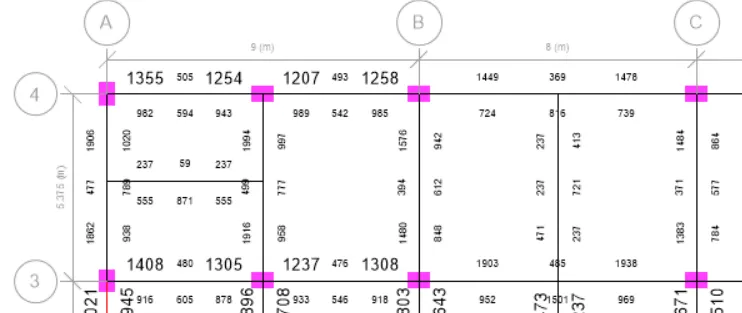
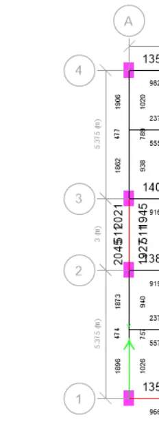
- Longitudinal reinforcement of the beam for Grid 3

- Shear Reinforcement of beam for Grid 3

- shear reinforcement at grid a
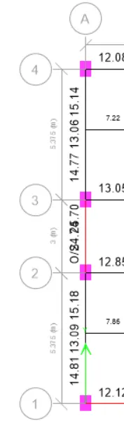
- The obtained are the information of said beams.
- After this we are seeing the mid sapn failure of the beam in grid A.
- Here O/S means overstressed
- The stress has increased beyond the allowable value thats why it impossible to calculate here
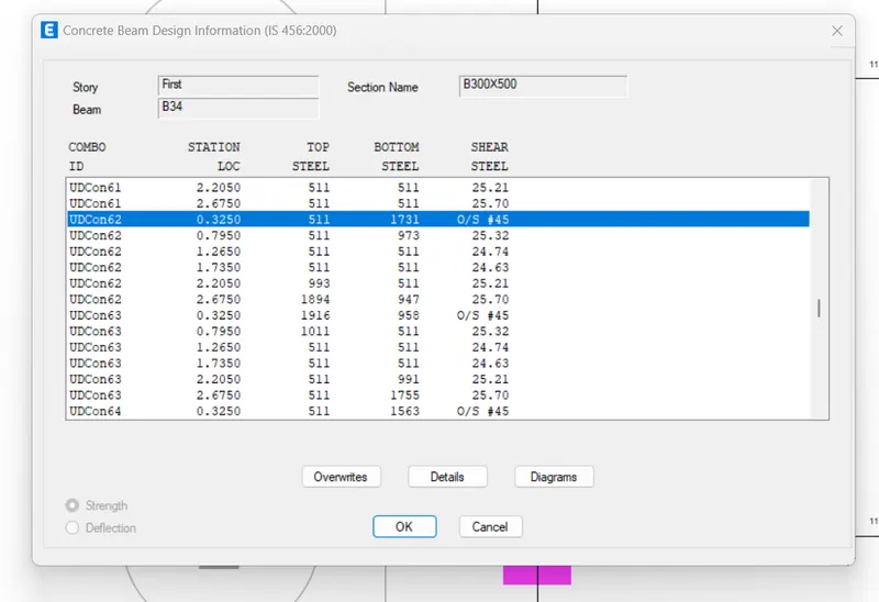
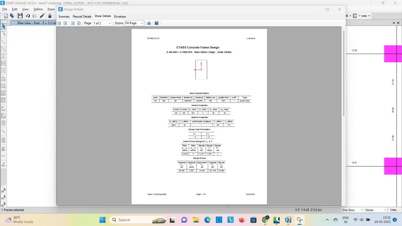
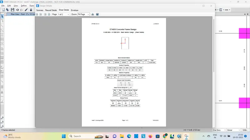
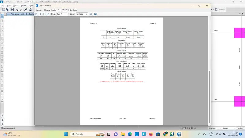
- Shear stress in load/area, We have to reduce the loading or increase the loading are the available suggestions as asked
- Shear capacity of the concrete, it varies according to the grade of concrete
- Instead of using M25 grade if used higher grade for this beam alone we can make the beam pass in the shear stress.
-
- For the calculation of maximum shear force .
- we are refering IS456-2002 clause 40.4
- And the formula is
Vus = (0.87fyAsvd)/Sv mm2
Where
fy = 415N/mm2
Asv = 151mm2
d= 450mm
Sv = 100mm
-
As per the observations from the drawing and IS Code
And
Vus = 245KN
- load combination
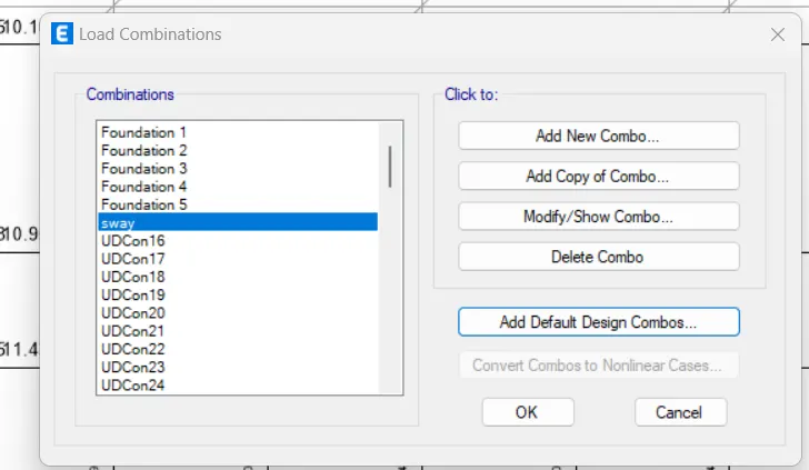
- next sway connection of shear and beam connection
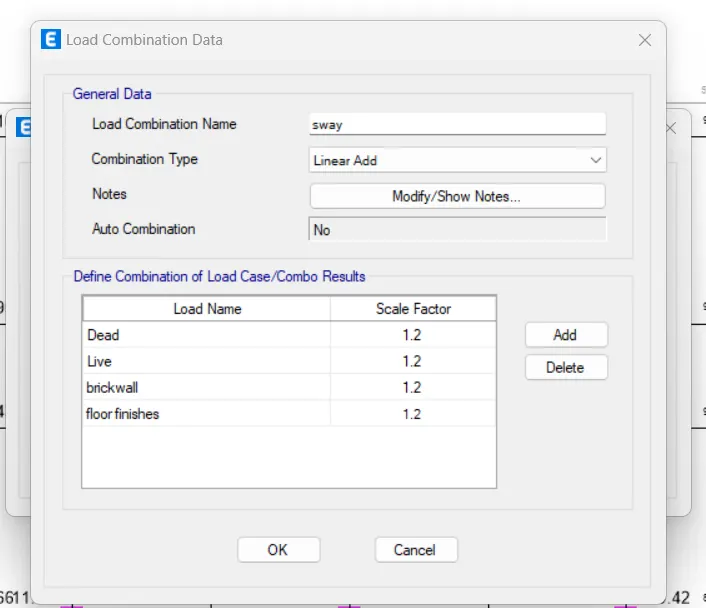
- sway shear right mbh =234kn
- mas=174kn mbs=155knm
- mbh= 293kn Lab =4.725kn
- Lab=4.725kn ld+1 =70kn
- vua=46kn vuu= 185kn
- vub= 230kn
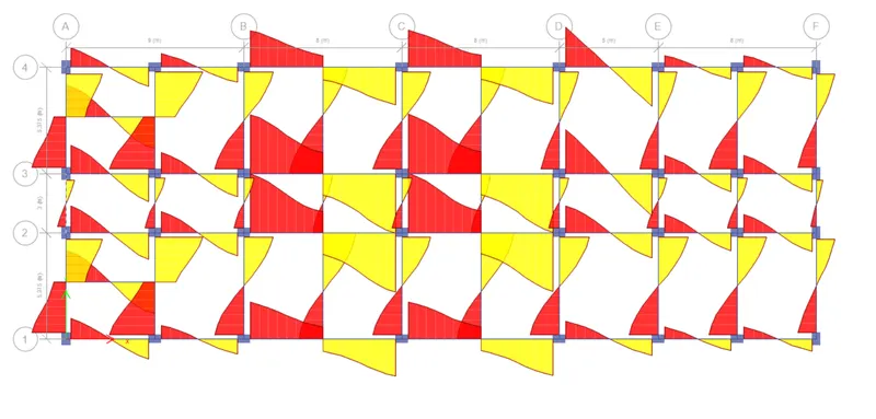
- sway shear of the diagram
-
- Result:
- The model was inserted.
- resolution was given.