Reinforcement Detailing of Beams from ETABS output
Aim: To run the analysis of a given model and degign moment resisting frame and provide the reasons for the issue descripted.
Introduction: In this challenge a given model Etabs will be run to analyse and design the structural diagram for 2 continous beam, they are : 1) 3 span continuous beam along grid A, 2) 7 span continuous beam along grid 3. Later provide reasons for failure of the middle span along grid A. What are the possible ways this issue can be resolved? and finally calculate value for maximum shear force in any one of the spans in both the continuous beams as per clause 6.3.3 (b) in IS 13920 – 2016. Also, confirm these values from shear force demand calculated by ETAB
Procedure:
To design the reinforcement for 1) 3 span continuous beam along grid A, 2) 7 span continuous beam along grid 3.
- Open the given Etab model and run the analysis. Now to achieve concrete frame design click on concrete frame design icon in the ribbon as shown in fig A.
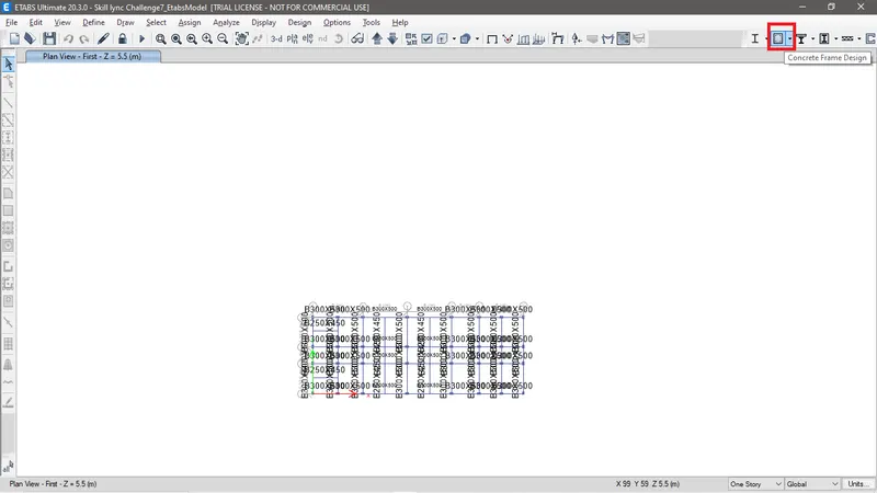
Fig A: Concrete frame design.
- We can see now in Fig b that the longitudinal reinforcement designs are achieve from concrete frame design execution.
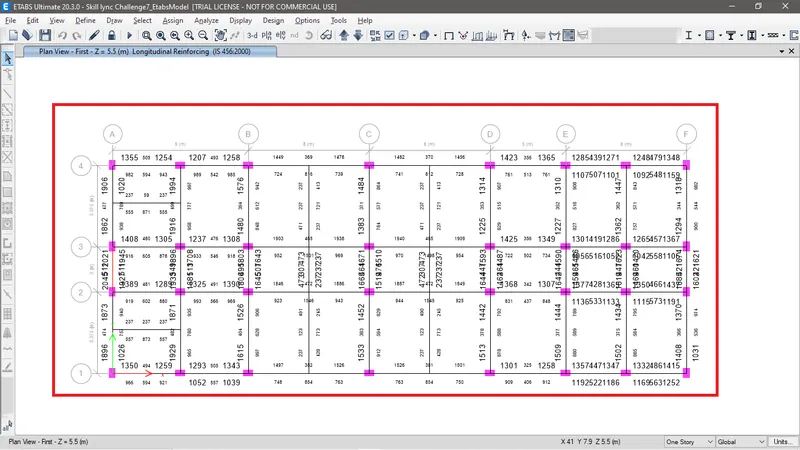
Fig B: Longitudinal reinforcement design.
- In order to achieve shear reinforcement deisgn click on the drop down box of the Concrete frame design and go to Display design info as shown in fig C.
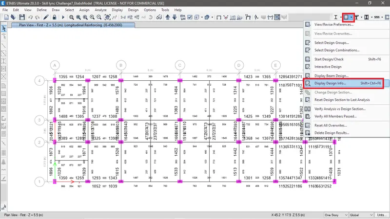
Fig B: Display design info.
- Now select Design output as Shear reinforcing as shown in fig C.
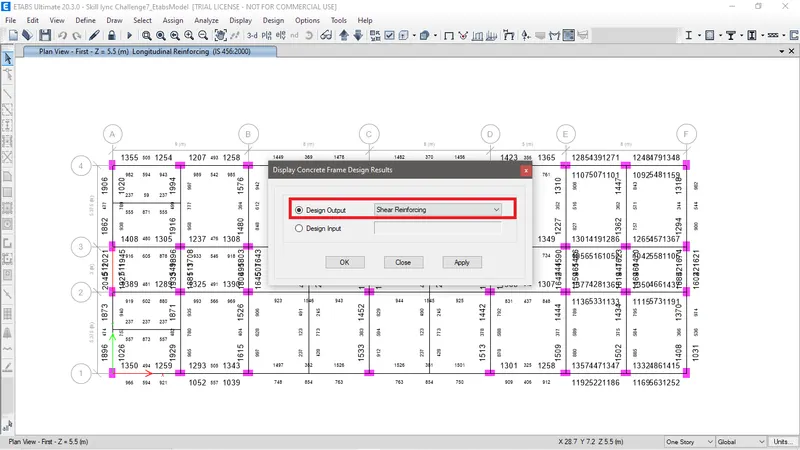
Fig C: Design output: Shear reinforcing.
- Now we have achieved design of shear reinforcement as shown in fig D.
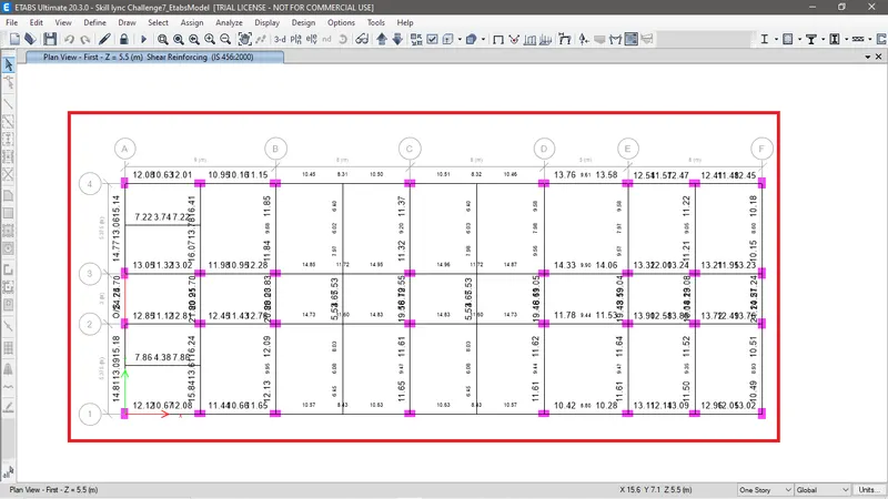
Fig D: Design of shear reinforcement.
- Fig E and F shows the detailed longitudinal and shear reinforcement of Grid A and grid 3.
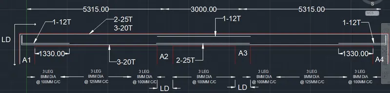
FigE: Grid A detail reinforcement.

FigF: Grid 3 detail reinforcement.
Provide reasons for failure of the middle span along grid A. What are the possible ways this issue can be resolved?
- The reason for the beam A2-A3 to failure is due to shear stress due to shear force and torsional force together exceeds maximum allowed as the result shown in fig G in Etabs.
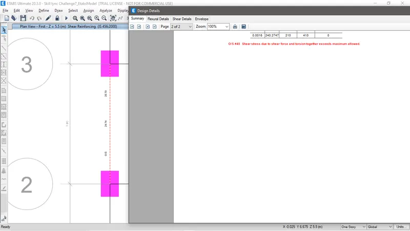
Fig G: Result by Etabs for the failure of the middle span beam A2-A3.
- The possible way to solve this issue is by reducing the load to that beam or by increasing the grade of the concrete for that particular failed beam only.
Calculate value of the maximum shear force in any one of the spans in both the continuous beams, as per clause 6.3.3 (b) in IS 13920 – 2016. Also, confirm these values from shear force demand calculated by ETABS.Please note that if longitudinal reinforcement provided is more than required (as per ETABS results), the shear force demand will vary from what is provided by ETABS.
- Fig H shows the formula to check the sway shear to left and right of a span
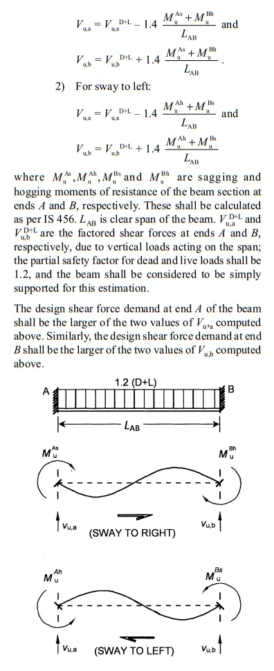
Fig H: Sway shear formula for Left and Right as per IS 13920
- To conduct shear check we need to provide sway load combination and with the help of the values achieved in the Etabs the sway shear check can be done. To add sway load combination go to Define tab > Load combination > Add new load combination and then define the the sway load combination as shown in fig I.
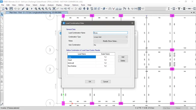
Fig I: Sway load combination
- Now go to member force diagram for frame select combo and then select combo sway and select shear 2-2 and click on apply. now we can see the frame diagram created and the values for it is achieved as shown in fig J.
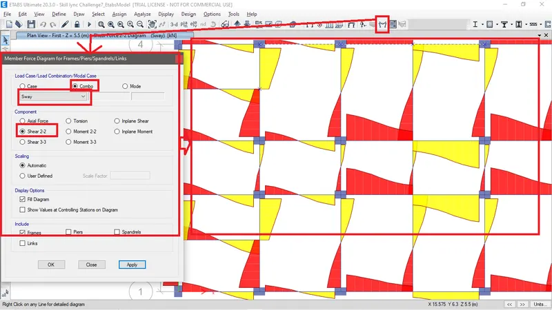
Fig J: Force digram for frame.
- Now right click the beam which is required to know the value of the shear force and moment at that point as shown in fig K.
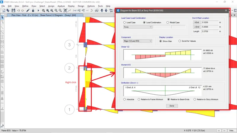
Fig K: Diagram for a beam.
Checking shear force for a beam A1-A2
Sway to right:-
V(u+a) = 86.9 KN, Mu (As) = 70.33 KN-m and Mu (Bh) = 72 KN-m, Vu,b = 91.98KN
Vu,a = 86.9 - 1.4*(70.33+72)/4.72 = 44.68 KN
Vu,b = 91.98+ 1.4*(70.33+72)/4.72= 134.20 KN
Sway to left:-
Vu,a = 86.9 + 1.4*(70.33+72)/4.72 = 44.68 KN
Vu,b = 91.98- 1.4*(70.33+72)/4.72= 129.12KN
The highest shear force achieved here is Vu,b i.e. 134.20KN.
Check for shear as per IS 456: 2000 as per the shear reinforcement provided in the beam.
The shear reinforcement provided in the beam is 3 legged 8mm dia.
Vus= 0.87*fy*Asv*d/Sv
Here fy= 415N/mm2, Asv=(3*3.14*8*8)/4=150.72mm2, d=500-38=462mm and Sv=100 (support section) and Sv=125 (Mid section)
Vus at support section
Vus= ((.87*415*150.72*462)/100)/1000=251.41Kn
Since the Vus at support section is greater than the highest Vub hence the shear reinforcement provided is safe.
Checking shear force for a beam C3-D3
Sway to right:-
V(u+a) = 150.61 KN, Mu (As) = 198.57 KN-m and Mu (Bh) = 193.30 KN-m, Vu,b = 149.18 KN
Vu,a = 150.61 - 1.4*(198.57+193.30)/7.35 = 75.97 KN
Vu,b = 149.18+ 1.4*(198.57+193.30)/7.35= 223.82 KN
Sway to left:-
Vu,a = 150.61 + 1.4*(198.57+193.30)/7.35 = 225.25 KN
Vu,b = 149.18- 1.4*(198.57+193.30)/7.35= 74.54 KN
The highest shear force achieved here is Vu,b i.e. 225.25KN.
Check for shear as per IS 456: 2000 as per the shear reinforcement provided in the beam.
The shear reinforcement provided in the beam is 3 legged 8mm dia.
Vus= 0.87*fy*Asv*d/Sv
Here fy= 415N/mm2, Asv=(3*3.14*8*8)/4=150.72mm2, d=500-38=462mm and Sv=100 (support section) and Sv=125 (Mid section)
Vus at support section
Vus= ((.87*415*150.72*462)/100)/1000=251.41Kn
Since the Vus at support section is greater than the highest Vub hence the shear reinforcement provided is safe.
Conclusion
In this challenge Beam of grid A and Grid 3 is provided with the details of reinforcement as per the Etabs designed.
Reason for the failure of the mid span is provided and shear check of one of the span for the grid is checked and found out to be safe.