Reinforcement Detailing of Beams from ETABS output
AIM:Detailed design of concrete buildings -1
PROCEDURE:
Detail design of beams in Etabs 2018.
The ETABS file for a G+4 building is provided. Run the analysis and design the RCC Moment ResistingFrame. The following challenge deals specifically with two continuous beams in the 1st floor.
1) 3 span continuous beam along grid A
2) 7 span continuous beam along grid 3
Address the following issues thereafter.
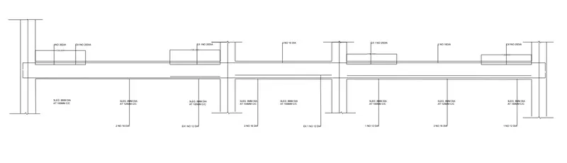
• Provide details of longitudinal and shear reinforcement for the two continuous beams. Sketch the beam elevation details or draft it using autocad software. A sample of how beam elevation details is prepared in consultancy firms is provided below. Participants can prepare it as per their preference:
PROCEDURE:
- Open the given etabs file, choose the run option, click on it.
- check the reinforcement values alonr the 3 span continuous beam along grid A and 7 span continuous beam along grid 3,
- also choose the reinforcement ,select shear reinforcement and apply,check the values of shear reinforcement,
- after taking that values manually calculated the number of required for top reinforcement as well bottom reinforcement and also as per shear requirement i design the stirrups with spacing also.
- check the sway condition with factor of 1.2 for all loads,
- after that calucated the existing shear capacity in beam as per drawing.
longitudinal beam reinforcement details(7 span continuous beam along grid 3):

longitudinal beam shear reinforcement details(7 span continuous beam along grid 3):

3 span continuous beam along grid A main reinfocement requirement.
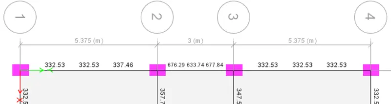
3 span continuous beam along grid A shear reinforcement requirement.
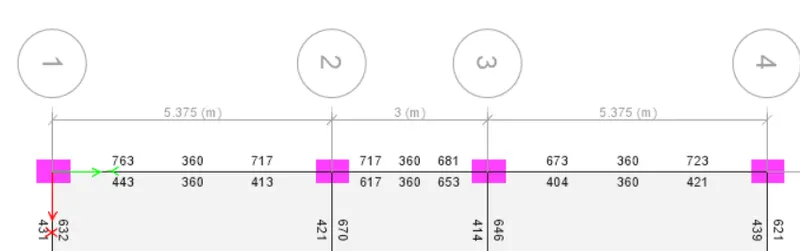
Manually designed required bars details:
along 7 span continuous beam along grid 3
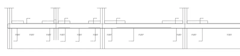
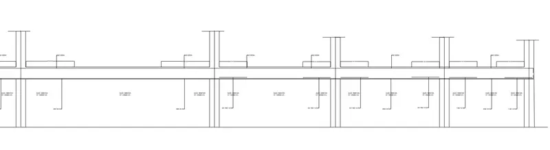
3 span continuous beam along grid A
Existing shear capacity in beams as per drawing :
Vus = 0.87 Fy Asv d/ Sv
Fy= 415 N/mm^2
Asv= 155mm^2
d= 450mm
Sv= 100mm
Vus= 251 KN
hence shear rebar drawing is okay as per IS-13920 Code guidance.