Project 1 _Creating an Architectural plan for the provided plot size and develop relevant basic structural drawings
AIM: Design and Draft a layout of a residential building
INTRODUCTION:
Design and Draft a layout of a residential building with the following details:
a. Plot Size: 60’x20’(18.3m x6m)
b. Orientation- Facing East
c. Develop the following: 1. Architectural Drawing (Floor Plan, Elevations, and Sections) 2. Structural Drawing (Column, Bean, Footing Plan)
PROCEDURE:
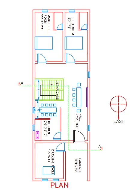
PLAN
- Choosing the dimensions in feet created the blocks of doors, windows, and beds.
- created the new layers for walls, doors, windows, beds, staircase, tv, and kitchen.
- as per the standard sizes of bedrooms and halls are created,
- the design is going as per Vastu and the entrance is placed on the east face
- parking place provided at the entrance,
- the total plan has 2 bedrooms, a kitchen with a dining hall, the main hall, a drawing room, and a parking area.
- all texts are created by using the MTEXT command,
- all dimensions are measured by DIMLINEAR COMMAND.
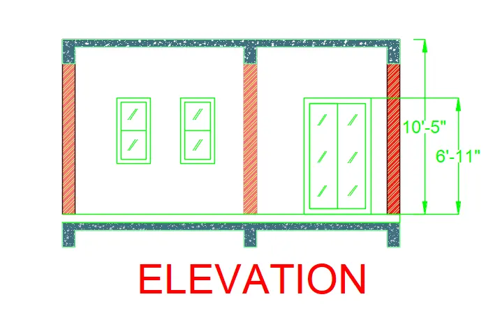
ELEVATION
- By using x line command all vertical lines are created from the plan,
- and horizontal lines are created by using levels,\
- from bottom DPC level up to 1'6",
- windows are created 3'offset from the DPC level,
- doors are created 6'11" from the DPC level,
- total height of the floor considered as 10'6",
- all measurements are created with help of the DIMLINEAR command.
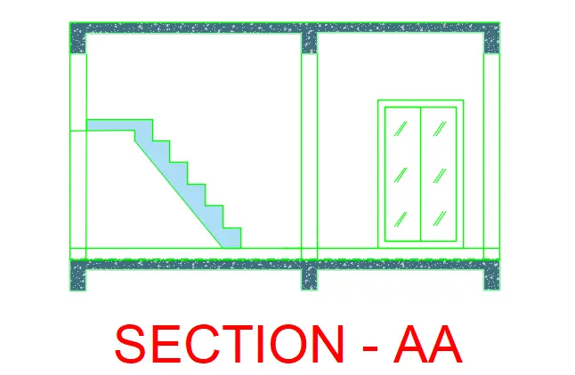
SECTION-AA
- By using the elevation all outer drawing is created with the same dimensions,
- By using the section line the section is created in those section steps and the main doors are visible,
- steps are created by using thread and rise dimensions,
- the main door created as per the elevation drawing,
- measurements are measured by the DIMLINEAR command.
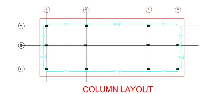
COLUMN LAYOUT:
- By using the plan choose the column positions,
- all columns are created and hatched with different colors,
- after that, by using lines the center line is drawn,
- by using DIM LINEAR AND DISCONTINUE command the dimensions are measured.
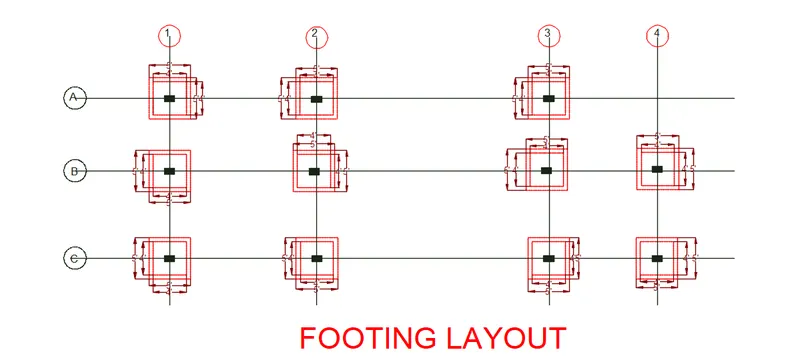
FOOTING LAYOUT:
- As per the plan, the columns are located by using columns,
- as per the standards the footing size was decided as 4'inside and 5' outside,
- the footing created one layer with os in red color,
- the dimensions are measured with the DIMLINEAR command created the layer of dimensions,
- all center lines are drawn by using the line command,
- the positions are marked with help of A, B, C, AND 1,2,3, AND 4.
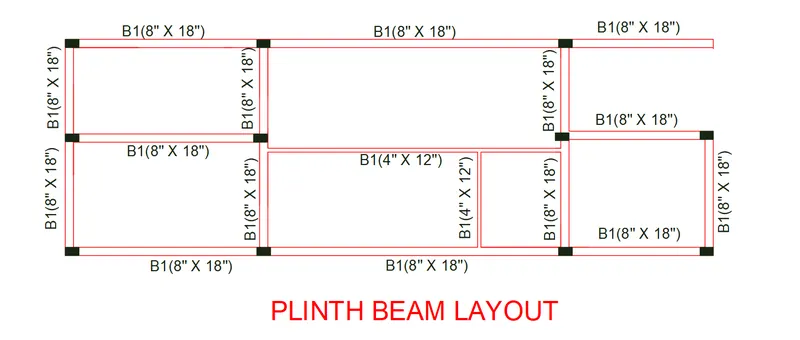
PLINTH BEAM LAYOUT:
- By using the plan, in the plans as per the walls the plinth beam is created,
- chose the all wall and copied separately,
- given layer to the plinth beam all lines are inserted here,
- given the size of plinth beams are two types one is B1(8"x18") and another one is B1(4" X12")
- all texts are texted by using MTEXT COMMAND,
- To mention every plinth beam dimensions copy option is used to paste the dimensions in front of the beam.
RESULT:
As per the challenge, East facing plan, elevation, and section are created, and as well created column layout, footing layout, and plinth beam layout are created.