Creating Kitchen layout, Hatching of Architectural elements and sectional view of an Industrial Building in AutoCad
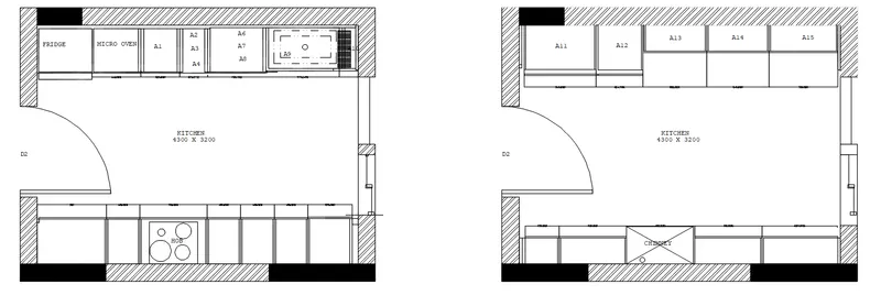
AIM: Create the layouts of the Kitchen and provide a hatches pattern.
INTRODUCTION:
Create the layouts of the Kitchen and provide a hatches pattern as shown. Also, use blocks wherever required. Provide appropriate dimensions in the plan. Assume the size of doors, appliances, and others as per the standards.
PROCEDURE:
- created the layout of the kitchen by using line, rectangle, and offset commands as per dimensions,
- door block is created by using the block command, and inserted by using the insert command,
- by using the hatch command hatching is done,
- selecting the hatch pattern solid and choosing the color is black selected the boundary as required,
- later selected the wall pattern chose the scale of 100 and pasted it in the specified location as per the drawing.
RESULT: Created the layouts of the Kitchen and provided a hatches pattern.
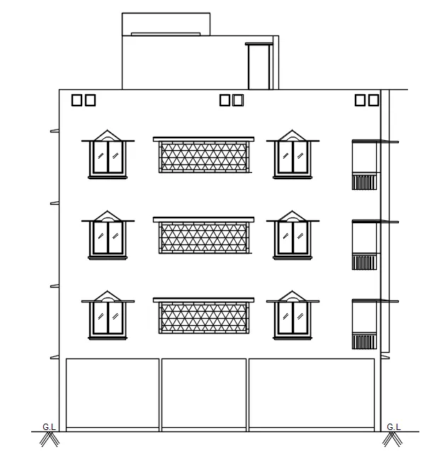
AIM: Create the elevation of the plan created in Challenge 7.
INTRODUCTION: Create the elevation of the plan created in Challenge 7 and apply proper hatch in the walls, doors, windows, and other architectural elements. Refer to the dimensions in Plans and sections in Challenge 7.
PROCEDURE:
- as per the challenge 7 plan by using lines command the elevation outer marks are created,
- by using offsets walls are created,
- created the window by using rectangle and line commands as well as offset commands,make it back by using the block command,
- bt using insert command block inserted at specified locations,
- at center architecture elevation created by using line and offset command,
- after that the corner portion is created by using the rectangle command and array command,
- finally, the by using hatch command selected the hatch visible in plan specified the boundaries click enter,
- the hatched portion copied for each portion.
RESULT: Created the elevation of the plan created in Challenge 7 and applied proper hatch in the walls, doors, windows,
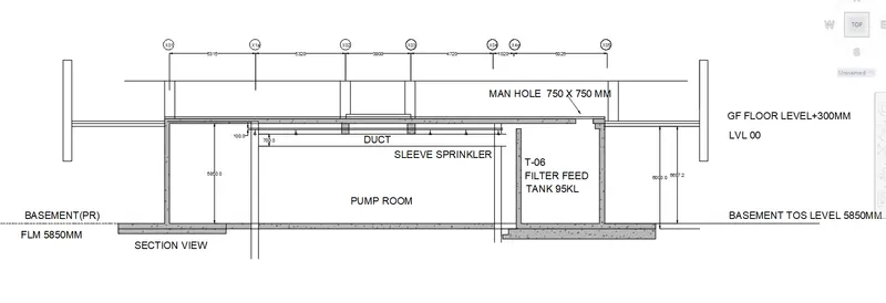
AIM: create the section view of an industrial building as shown in the figure.
INTRODUCTION:
create the section view of an industrial building as shown in the figure. provide appropriate hatches and dimensions whenever required. also, provide annotations to the drawing.
PROCEDURE:
- by using line command the outer view of industrial elevation is created,
- by using the Multiline command the walls and beams are created by varying the scale,
- by using the offset the outer portions are created,
- by using a rectangle the concrete portions are created,
- by using the text command text is inserted,
- by using the dim command the distances are measured,
- by using the hatch command hatching happened, by clicking hatch selected the hatch as concrete and choose the specific locations, and attached the color as grown, and with a transparency of 40% click on enter.
RESULT: created the section view of an industrial building as shown in the figure. provided appropriate hatches and dimensions whenever required. also, provide annotations to the drawing.