Reinforcement Detailing of Beams from ETABS output
Aim:
To design a RC continous beam from a G+4 building and sketching the elevation of reinforcement diagram, addressing the reason for failure in middle span along grid A and suggesting the solution for the problem, checking the shear reinforcement provided is safe with respect to ETABS results.
Procedure:
Before start analyzing the ETABS model, there are certain basic criteria to be assumed for a RC beam detailing.
i.Minimum reinforcement for shrinkage and temperature
ii.Reinforcement required for limiting crack-width
iii.Ultimate limit state design rebar requirement
iv.Ductility reber requirement
From all the above factors the greater of all should be considered for designing a RC beam.
1.Minimum longitudinal reinforcement as per IS 13920-2016 Clause 6.2.1
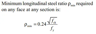
using the above formula, As = 360 mm2
2.Minimum shear or transverse reinforcement as per IS 456-2000 Clause 26.5.1.6 (Assuming 1000mm spacing)
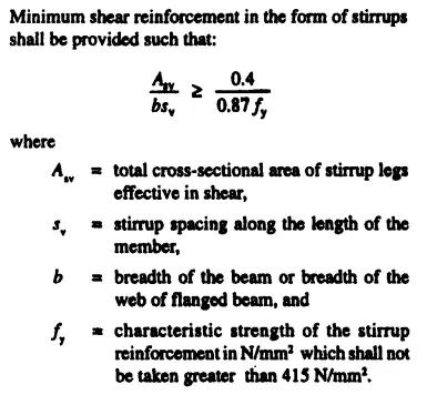
From the Model breath b= 300mm
fy = 415 N/mm2
using the formula, Asv = (0.4x300x1000) / (0.87x415)
Asv = 332 mm2
3.Development length as per IS 456-2000 Clause 26.2.1
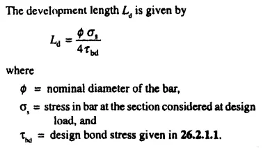
simplifing the formula, Ld = 41 x diameter of bar
Once the given ETABS model is analyzed and concrete frame design is done for every frame section, the longitudinal and shear reinforcement detailing for the required beam is checked. The screen shot of required beam section is provided below:
Longitudinal reinforcement detail of Grid 3:

Shear reinforcement detail of Grid 3:

Longitudinal reinforcement detail of Grid A:

Shear reinforcement detail of Grid A:

We encounter an issue in Grid A where one of the span in continous beam, the shear reinforcement is not designed. Taking a look at ETABS reinforcement detailing, it shows that the combination of shear stress and torsional stress exceeds the permissible stress limits assigned as per codal provisional. Shear is directly proportional to load and inversely proportional to area, it states that load increases the shear but we cannot reduce the load applying on the member. Solution to this issue is to increase the area of the beam so that the span will resist the shear stress acting on it and providing the closely spacing stirrups will overcome this issue.
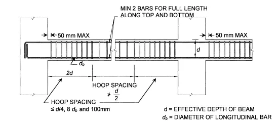
Close spacing of links:
1.Spacing of links over a length of 2d at either end of a beam shall not exceed,
i.d/4
ii.8 times the diameter of the smallest longitudinal bar
iii.100mm
2.The first link shall be at a distance not exceeding 50mm from the joint face.
3.Closely spaced links shall be provided over a length equal to 2d on either side of the section where flexural yielding may occur under earthquake effects. Over the remaining length of the beam, vertical links shall be provided at a spacing not exceeding d/2.
Checking the span against sway conditions as per IS 13920-2016 clause 6.3.3(b)
Sway shear force to right:
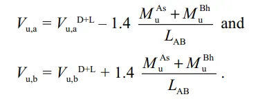
MuAs = 174 KN.m
MuBh = 293 KN.m
LAB = 4.725 m
VD+L = 92 KN
We got all the above values from the ETABS analysis results and submitting in the above equation we got,
Vu,a = 46 KN
Vu,b = 230 KN
Sway shear force to left:
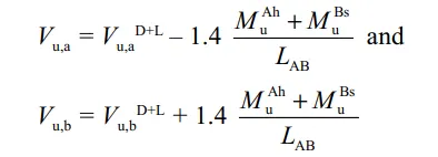
MuAh = 234 KN.m
MuBs = 155 KN.m
LAB = 4.725 m
VD+L = 70 KN
We got all the above values from the ETABS analysis results and substituting in the above equation we got,
Vu,a = 185 KN
Vu,b = 45 KN
Check against shear reinforcement:
Shear capacity in beam as per IS 456-2000 Clause 40.4,
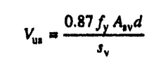
fy = 415 N/mm2
Asv = total cross sectional area of stirrup legs
= 3x(Area of rebar)
= 3x∏ r2
Since we have 3 legged stirrups of 8mm dia.
Asv = 151mm2
d = 450mm (Effective depth of beam)
Sv = 100mm
Substituting the above values in the formula we got,
Vus = 245 KN
Hence 230 KN < 245 KN
The maximum shear capacity arriving is 230 KN in the beam and hence the designed shear capacity is greater than that. Hence Safe.
Result:
Design of RC continous beam from a G+4 building and sketching the elevation of reinforcement diagram, addressing the reason for failure in middle span along grid A and suggesting the solution for the problem, checking the shear reinforcement provided is safe with respect to ETABS results are arrived.