Reinforcement Detailing of Beams from ETABS output
AIM: DETAIL DESIGN OF BEAMS IN ETABS 2023
THE ETABS FILE FOR A G+4 BUILDING IS PROVIDED. RUN THE ANALYSIS AND DESIGN THE RCC MOMENT RESISTING FRAME. THE FOLLOWING CHALLENGE DEALS SPECIFICALLY WITH TWO CONTINUOUS BEAMS IN THE 1ST FLOOR.
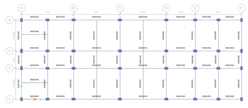
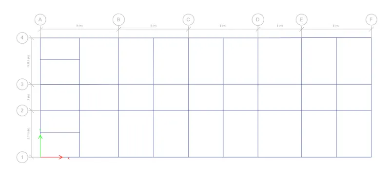
- 3 SPAN CONTINUOUS BEAM ALONG GRID A
- 7 SPAN CONTINUOUS BEAM ALONG GRID 3
ADDRESS THE FOLLOWING ISSUES THEREAFTER.
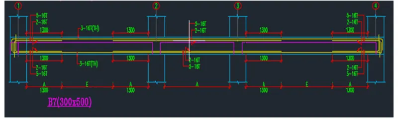
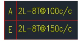
- PROVIDE DETAILS OF LONGITUDINAL AND SHEAR REINFORCEMENT FOE THE TWO CONTINUOUS HOW BEAM ELEVATION DETAILS IS PREPARED IN CONSULTANCY FIRM IS PROVIDED BELOW. PARTICIPANSTS CAN PREPARE IT AS BER THEIR PREFERENCE
- PROVIDE REASONS FOR FAILURE OF THE MIDDLE SPAN ALONG GRID A. WHAT ARE THE POSSIBLE WAYS THIS ISSUE CAN BE RESOLVED?
- CALCULATE VALUE OF THE MAXIMUM SHEAR FORCE IN ANY ONE OF THE SPANS IN BOTH THE CONTINUOUS BEAMS, AS PER CLAUSE 6.3.3 (b) IN IS 13920 – 2016 ALSO CONFIRM THESE VALUES FROM SHEAR FORCE DEMAND CALCULATED BY ETABS. PLEASE NOTE THEAT IF LONGITUDINAL REINFORCEMENT PROVIDED IS MORE THAN REQUIRED (AS PER ETABS RESULT) THE SHEAR FORCE DEMAND WILL VARY FROM WHAT IS PROVIDED BY ETABS.
ANS:
- INTRODUCTION:
- The design and construction of reinforcement concrete building shall be governed by the provision of IS 456:2000
- Steel reinforcement of grade Fe 415 or less can be used
- Strong steel is not preferable to low strength steel in earthquake – prone region because the typical stress-strain curve of low steel shows the following advantages a) long yield b) greater breaking strain c) less strength gain after the first yield
- DESIGN RULE OF ANY REINFORORCED CONCRETE MEMBER:
- Minimum reinforcement for shrinkage & temperature
- Reinforcement required for limiting crack-width
- Ultimate limit state design rebar requirement
- Ductility rebar requirement
- Above four point whichever is greater should be drawn in RC beam detailing
- Minimum longitudinal reinforcement as per IS – 13920-2016 clause 6.2.1 As = 360mm^2
- Minimum shear (or) transverse reinforcement as per IS-456-2000 clause 26.5.1.6 ( assuming 1000mm spacing in the formula) Asv =332mm^2
- Development length as per IS-456-2000 clause 26.2.1 Ld = 41 x diameter of bar
- PROCEDURE:
- First download the etabs drawing challenge file from the week 8 challenge and open it in etabs software
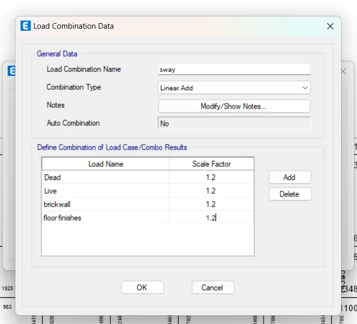
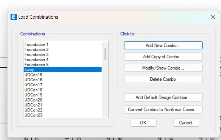
- Next, we have to check the load combination as shown below
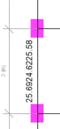
- Next we have to start the beam design by selecting start design/check option as shown below
- After the complete of the beam design we need to select the display design info option as shown below
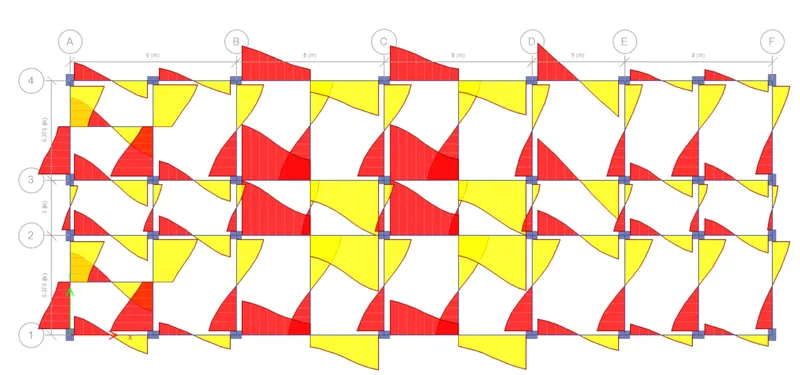
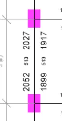
- After selecting the display option the new tab appears in that we select the longitudinal reinforcement in the design output and click on the ok button as shown below
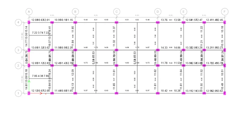
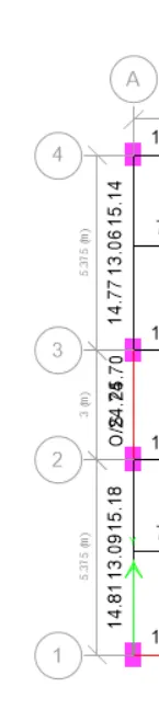
- Next longitudinal reinforcement details as appears
 \
\
- LONGITUDINAL REINFORCEMENT:
- The top as well as bottom reinforcement shall consists of at least two bars through out the member length
- By pressing F5 button star the modelling
- Concrete design is done for this model
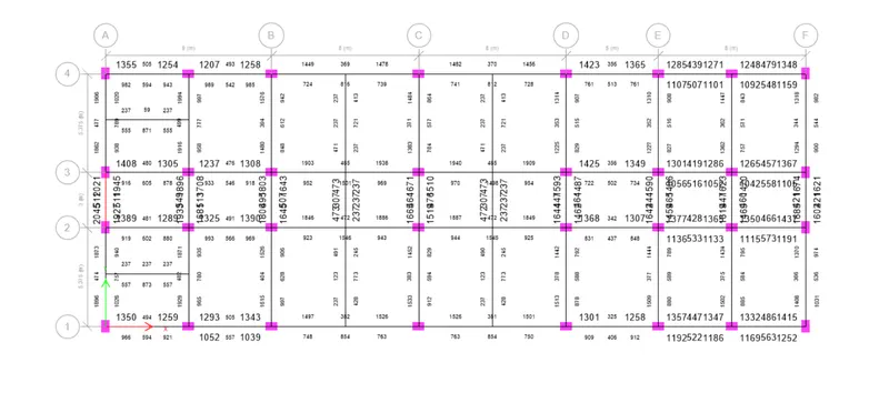
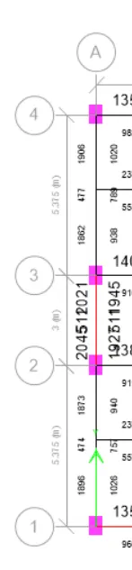

- Note:
- Ast for 32mm diameter = 804.24mm^2
- Ast for 25mm diameter = 490mm^2
- Ast for 20mm diameter = 314mm^2
- Ast for 16mm diameter = 201mm^2
- Ast for 12mm diameter = 113mm^2
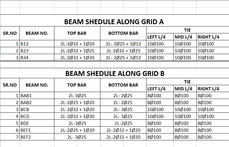
- We have design the longitudinal bars as of following:
- SHEAR REINFORCEMENT:
- FOR GRID A,
- Hogging capacity of beam =- 288knm
- Sagging capacity of beam = 163knm
- Shear force for 1.2(Dl + LI) combination
- Shear force from Etan analysis = 93.8kn
- Clear span 5.375
- As per IS 13290 – 2016 clause 6.3.3
- Sway shear at left = 970.9 KN
- Sway shear at right = 905.8KN

- FOR GRID 3
- Hogging capacity of beam = -233knm
- Sagging capacity of beam = 162knm
- Shear force for 1.2 (DI + LI) combination
- Shear force from etab analysis = 71.4kn
- Clear span 4.5
- As per IS 13290 – 2016 clause 6.3.3
- Sway shear at left = 93.8kn
- Sway shear at right = 49kn
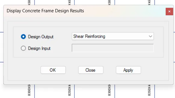
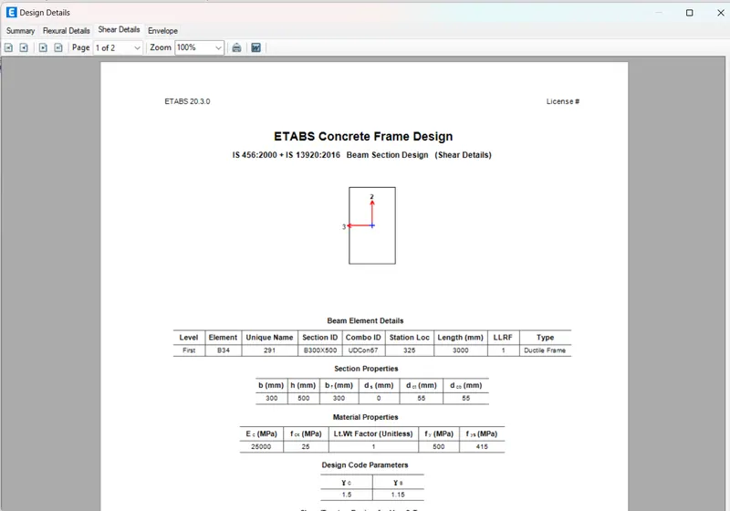
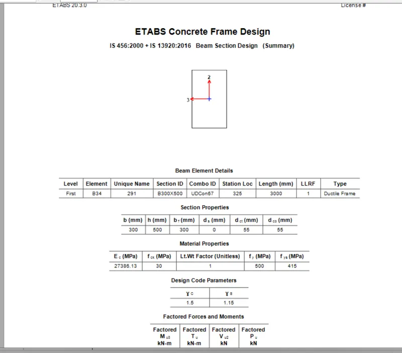
- After providing the beam reinforcement details, we select the beam right click on the beam then the new tab appears as shown below
- Next, we need to click on the details option in concrete beam design tan as shown below
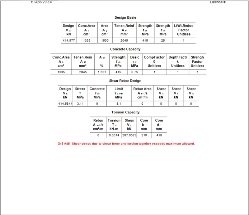
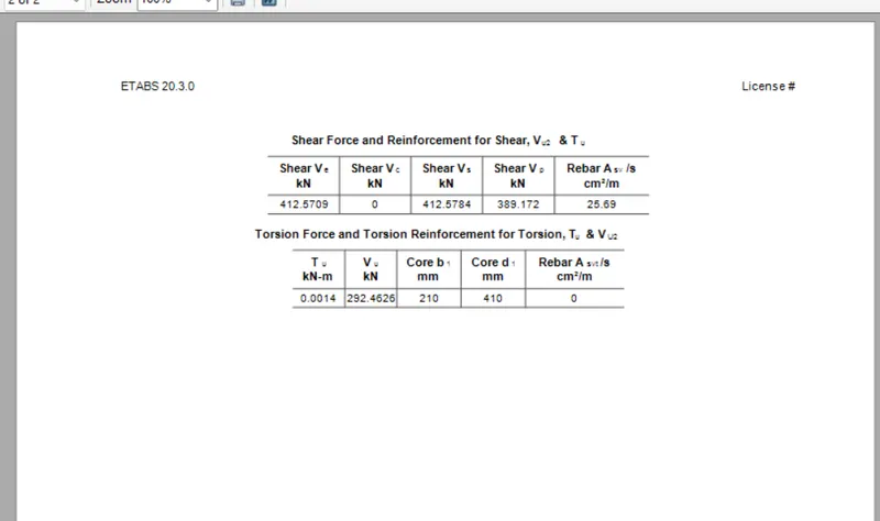
- Next shear details will be visible as shown below
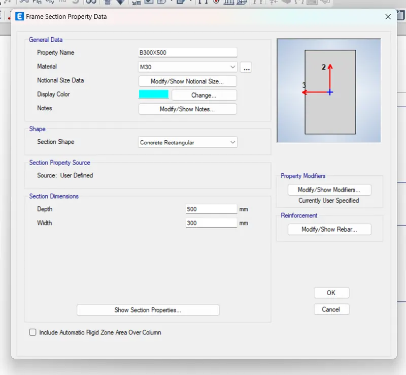
- MIDDLE SPAN OF GRID A FALIURE SOLVED
- Middle span of the grid a is over stressed at the joint top and bottom
- We can resolved this failure by changing default grade M25 to higher grade M30 so that the beam can pass in shear stressed
- We given as follow:
RESULT:
- The beams are designed as per the code in etabs software
- Provided the details of longitudinal and shear reinforcement for the two continuous beam
- And also calculated the value of maximum shear force in the continuous beam using the Etabs software