Reinforcement Detailing of Beams from ETABS output
Aim: To provide a detail design of beam using Etab
Software that i used---Etab
step by step procedure
open the given model file in Etab
select the beams which we are going to design.
hide all other elements.
run analysis
click design concrete frame
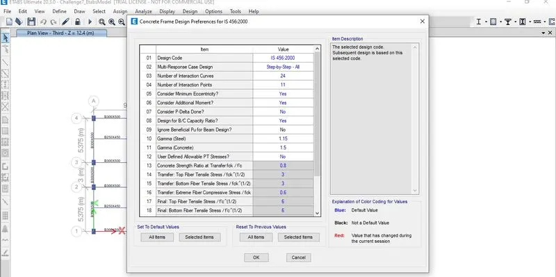
check the design preferences .
check the reinforcement details in which the Etab provided should satisfy the code standard
minimum reinforcement =0.24√fck/fy
=0.24x5/500
=2.4 x 10^-3 (ratio)
gross section of beam=300x500
minimum reinforcement =2.4x10^-3 x300x500
=360 mm2
maximum steel ratio=3750 mm2
minimum shear reinforcement as per Is456-2000
Asv=332 mm2
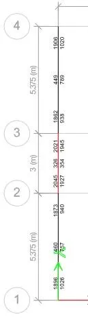
select the design information----longitudinal reinforceing
if we see in Etab reinforcement details the longitudinal reinforcement at any section is not less than 360mm2 and exceed 3750 mm2.
so etabs follow the standards.
longitudinal reinforcement provided should more than the etab reinforcement should not too much it effect in the shear demand.

select the design information-shear reinforcement.


Grid A
top longitudinal reinforcement ---2045
longitudinal provided--(3.14x0.25x20^2x4)+(3.14x0.25x20^2x3)
=>2200 provided
capacity should me more than demand
for shear reinforcement
In grid A shear 3-2 beam is over stress .
exceeded force acting on it.
we need change the grade of cncrete for it.
maximum shear ---15.18----(3.14*0.25*1*2)/0.1 cm2/m.
provided----18.8------(3.14*0.25*0.8^2*3)0.1 cm2/m
3 leg 8mm dia @100mmc/c are going to provided.
Grid B
top longitudinal reinforcement ---1940
longitudinal provided--(3.14x0.25x20^2x3)+(3.14x0.25x25^2x2)
=>1948 provided
capacity should me more than demand
for shear reinforcement
In grid A shear 3-2 beam is over stress .
exceeded force acting on it.
we need change the grade of cncrete for it.
maximum shear ---14.96----(3.14*0.25*1*2)/0.1 cm2/m.
provided----18.8------(3.14*0.25*0.8^2*3)0.1 cm2/m
3 leg 8mm dia @100mmc/c are going to provided.
Take reinforcement info in the ETAB
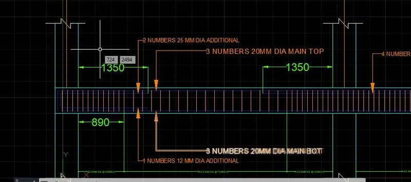
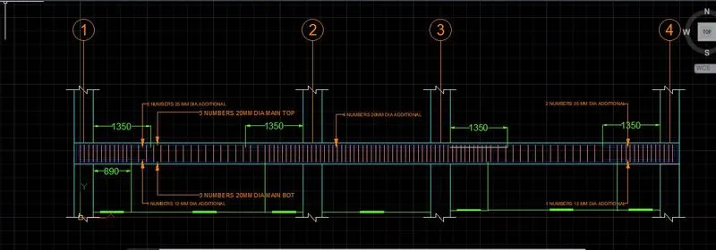
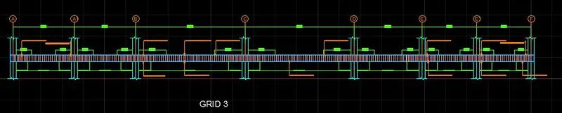
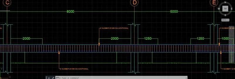
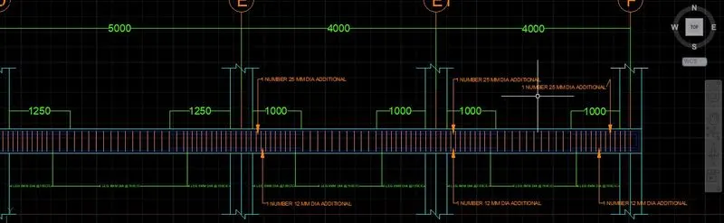
sketch the reinforcement detailing in the Autocad.
additional bar should not exceed L/4.
As per is 13920 -2016 confining reinforcement details
from face of column face 2d distance vertical reinforcement have to kept.
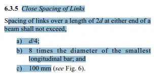
i have choosen 100 mm spacing
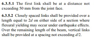
i have provided 175 mm spacing which is less than max 225 mm to the remaining length (≠2d)
Calculate value of the maximum shear force
sway to right
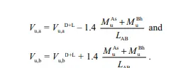
Mas=Z*As*fy*d
=174 KNm
Mbh=Z*As*fy*d
=293 Knm
Lab=4.725m
Vd+1=92 kn
Vua=46kn
vub=230 kn
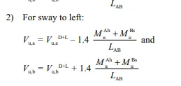
Mas=Z*As*fy*d
=234 KNm
Mbh=Z*As*fy*d
=155 Knm
Lab=4.725m
Vd+1=70 kn
Vua=185kn
vub=45 kn
maximum shear force=234 knm
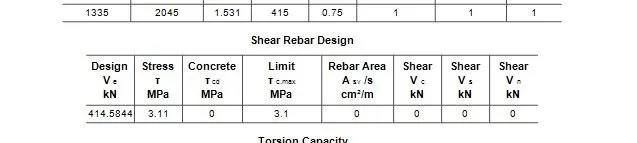
Provide reasons for failure of the middle span along grid A. What are the possible ways this issue can be resolved
A.shear force acting on the beam is more
so that it exceed the limit of stress
as per code for m25 grade concrete stress have to maintain below 3.1but incase it is exceeded.
remedies
use m30 grade concrete for this beam.

Result: I provided a detail design of beam using Etab.
sketch using AutoCAD