Reinforcement Detailing of Beams from ETABS output
Challenge 7 – Detailed design of concrete buildings -1
Detail design of beams in Etabs.
The ETABS file for a G+4 building is provided. Run the analysis and design the RCC Moment Resisting Frame. The following challenge deals specifically with two continuous beams in the 1st floor.
1) 3 span continuous beam along grid A
2) 7 span continuous beam along grid 3
• Provide details of longitudinal and shear reinforcement for the two continuous beams. Sketch the beam elevation details or draft it using autocad software.
Answer:
Aim: To analyze the given G+4 building and to provide details of longitudinal and shear reinforcement for the two continuous beams. To draft it using autocad software.
Procedure:
1. Open given G+4 building and run the analysis.
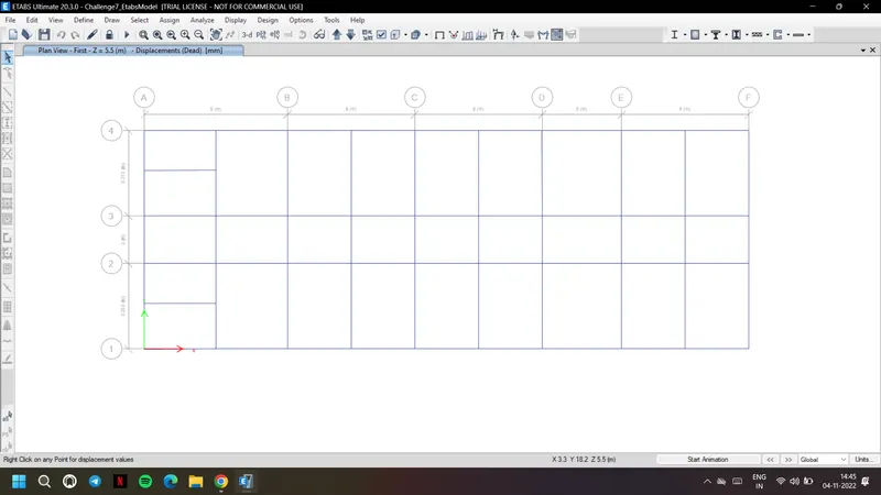
2. Go to concrete frame design and display design info, choose longitudinal reinforcement to get the results.
3. Again choose shear reinforcement to get details of shear reinforcement
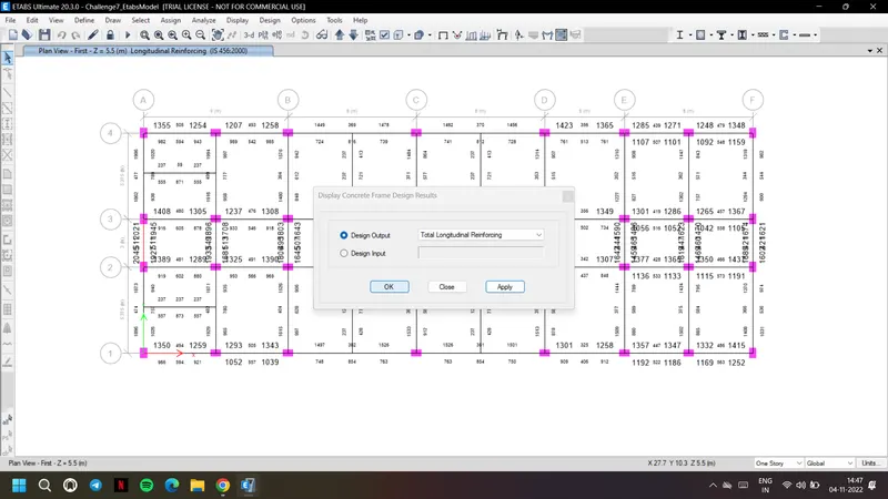
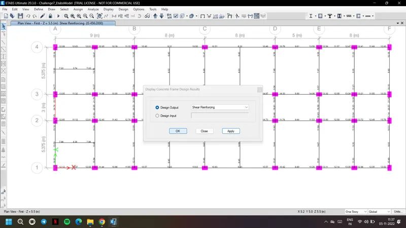
4. The Longitudinal Reinforcement for 3 span continuous beam along grid A
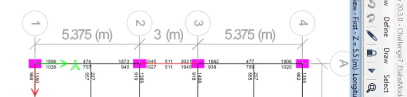
The Shear Reinforcement for 3 span continuous beam along grid A
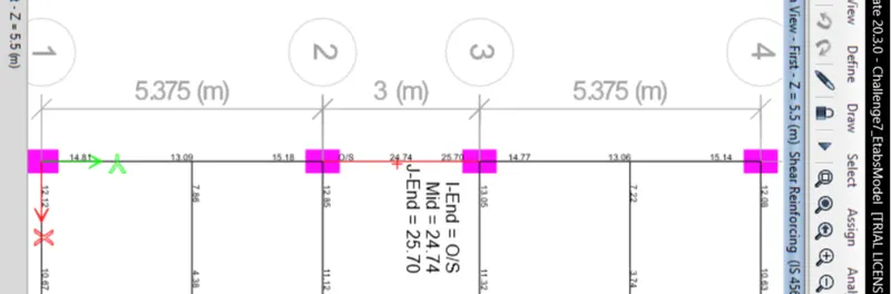
Table for longitudinal and shear reinforcement for 3 span continuous beam along grid A
| Sl.No | Beam Length | Beam Number | Load Combination | Longitudinal Reinforcement at Top and Bottom of the Beam in Mm^2 | Shear Reinforcement in CM^2 | Equivalent Shear in KN |
| 1 | 5.375 | B33 | UDCon67 = 1.5(DL+LL+WALL+FF+Eqy-) | 1896 and 948 | 14.79 | 237.5 |
| 2 | 3 | B34 | UDCon67 = .5(DL+LL+WALL+FF+Eqy-) | 2045 and 1022 | Over Stressed | 414.6 |
| 3 | 5.375 | B38 | UDCon66 =.5(DL+LL+WALL+FF-Eqy-) | 1906 and 953 | 15.12 | 242.75 |
5. The Longitudinal Reinforcement for 7 span continuous beam along grid 3

The Shear Reinforcement for 7 span continuous beam along grid 3

Table for longitudinal and shear reinforcement for 7 span continuous beam along grid B
| Sl.No | Beam Length | Beam Number | Load Combination | Longitudinal Reinforcement at Top and Bottom of the Beam in Mm^2 | Shear Reinforcement in CM^2 | Equivalent Shear in KN |
| 1 | 4.5 | B24 | UDCon57 = 1.5(DL+LL+WALL+FF-Eqx) | 1048 and 704 | 13.05 | 209.6 |
| 2 | 4.5 | B29 | UDCon57 = 1.5(DL+LL+WALL+FF-Eqx) | 1308 and 654 | 12.05 | 193.55 |
| 3 | 8 | B69 | UDCon56 = 1.5(DL+LL+WALL+FF+Eqx) | 1938 and 969 | 14.45 | 232 |
| 4 | 8 | B70 | UDCon57 = 1.5(DL+LL+WALL+FF-Eqx) | 1940 and 970 | 14.45 | 232 |
| 5 | 5 | B73 | UDCon57 = 1.5(DL+LL+WALL+FF-Eqx) | 1425 and 713 | 13.67 | 219.46 |
| 6 | 4 | B14 | UDCon57 = 1.5(DL+LL+WALL+FF-Eqx) | 1301 and 650 | 13.15 | 211.14 |
| 7 | 4 | B16 | UDCon56 = 1.5(DL+LL+WALL+FF+Eqx) | 1367 and 684 | 13.08 | 210 |
6. First need to examine the shear and longitudinal reinforcement obtained from ETABS.
7. Note down the longitudinal reinforcement required for beam at top and bottom and shear reinforcement required
8. Made table for the values which is provided above
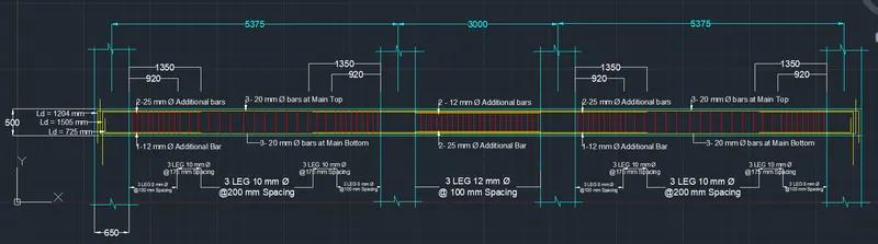
9. Now for shear reinforcement of A grid continuous beams, 3 legged 8 mm diameter bars placed with 100mm ifor the distance of 2d ie., 920mm
10. The shear force calculated would be 250KN which is more than the shear force acting on each side of beam from ETABS
11. So both sides 3 legged 8mm diameter bars with 100mm soacing is placed for 920 mm distance
12. For L/4 ie., 1350 mm distance on both sided 3 legged 10mm diameter bars with 175mm spacing is choosen
13. The shear obtained for that is 224 KN which is greater than the shear stress on beams from ETABS
14. For the remaining middle portion 3 legged 10mm diameter bars with 2oomm soacing is adopted
15. The shear for that is 196KN which is satisfies, these are calculated by formula Vus = o.87xfyxAsvxd/sv.
16. For beam 33 and 38 the same shear reinforcement is provided as mentioned above
17. For B34 as it is failing in shear for reinforcement is required and 3 legged 12mm diameter with 100mm spacing is adopted
18. Coming to the longitudinal bars, at top and bottom the main reinforcement of 3 - 20 mm diamter bars is placed
19. Along with that to satisty the steel requirement as per ETABS values as mentioned above in the table
20. For L/4 length the additional bar of 2-25 mm diameters placed at top and 1-12 mm diameter bars placed at bottom for both B33 and B38 beams
21. For beam B34, middle span beam along with these extra bars another additional bars also placed to satisfy steel requirement
22. 2-12 mm diameters bars at top and 2 -25 mm diameter bars at bottom are placed for middle span beam as shown below
22. According to code when there are two or more rows of bars then the bars needs to be kept at minimum vertical distance of 15mm or 2/3 height of maximum diameter of bars
23. So all the vertocal bars are kept at distance of 20 mm
24. The anchorage length is calculated by formula given in IS 456:2000 in clause 26.2.1 and maintained that for all the bars
25. Similar steps are followed and calculations are done for the 7 span continuous beam of B grid and obtained the longitudinal and shear reinforcement
Details of longitudinal and shear reinforcement for the 3 span continuous beam along grid A
Details of longitudinal and shear reinforcement for the 7 span continuous beam along grid B
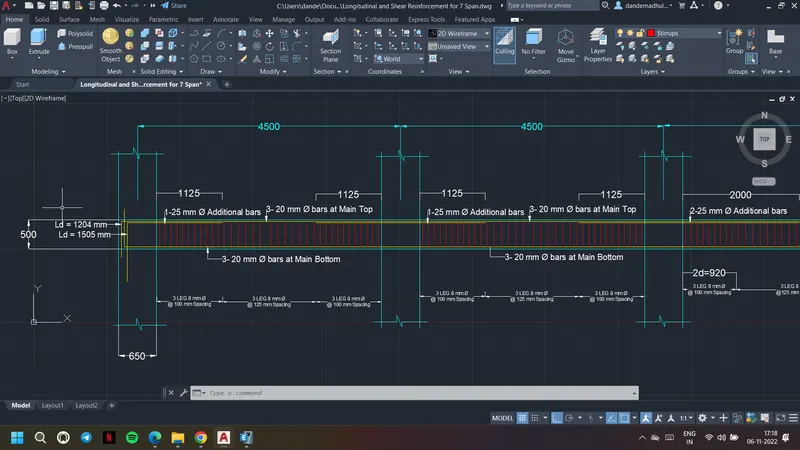
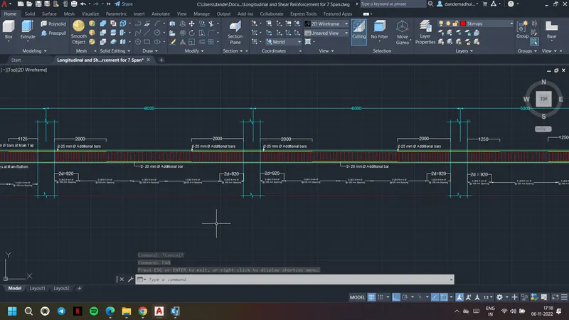
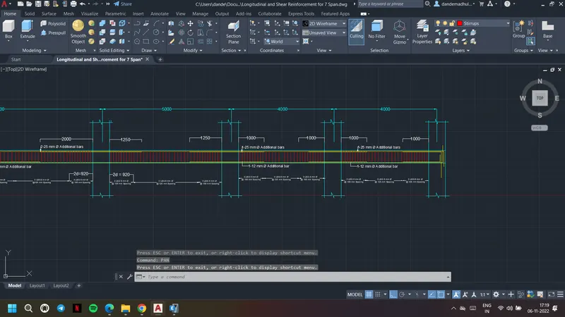
Result: Provided the details of longitudinal and shear reinforcement for the two continuous beams. Drafted it using autocad software.
• Provide reasons for failure of the middle span along grid A. What are the possible ways this issue can be resolved?
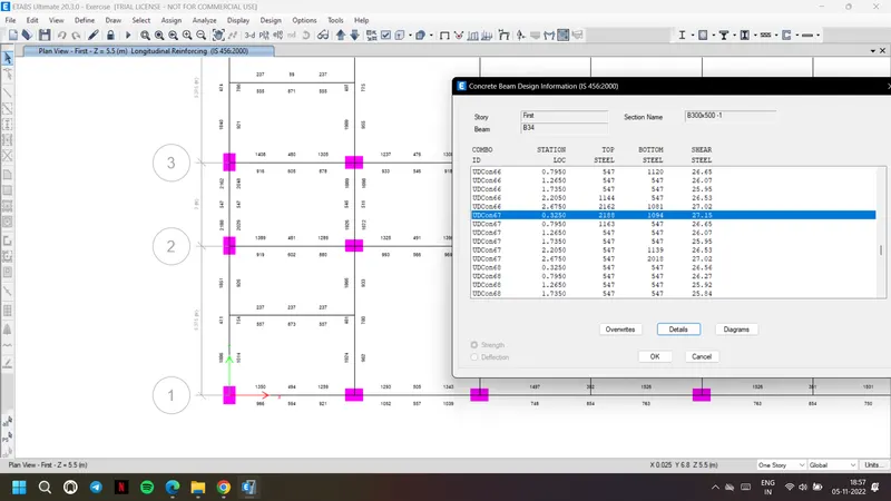
1. We can observe that the beam of middle span along grid A has failed.
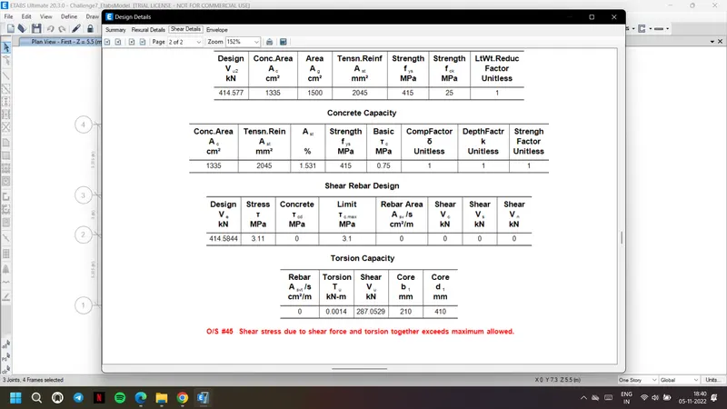
2. The beam has failed due to over stress i.e., due to high shear force of 414.6 KN which resulted in failure of beam before its fail in flexure
3. Shear stress can be reduced by reducing the load or increasing the area of beam
4. Shear capacity of the beam can be increased to avoid this failure. Shear capacity varies with grade of concrete, we can increase shear capacity of the beam by increasing its grade to avoid the failure.
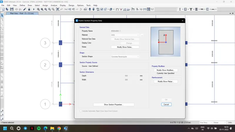
5. I have saved the challenge7 file as a new file and changed the concrete grade for mid span beam of grid A to M30 from M25.
6. Ran the analysis, it can be seen that the beam has now okay and was not having any failure because of high shear.
• Calculate value of the maximum shear force in any one of the spans in both the continuous beams, as per clause 6.3.3 (b) in IS 13920 – 2016. Also, confirm these values from shear force demand calculated by ETABS.
Aim: To calculate value of the maximum shear force in any one of the spans in both the continuous beams and to compare them with the shear force demand calculated by ETABS.
Procedure:
1. For calculation of maximum shear force as per clause 6.3.3 of IS 13920 2016, we need to add new load combination to find out the sway shear
2. Load combination would be 1.2 dead load + 1.2 Live load + 1.2 Wall + 1.2 Floor finishes
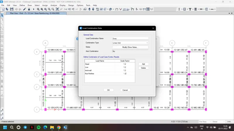
3. Now save the changes and run the analysis. Go to display frame/link forces option, choose sway shear load conbination
4. Choose component as shear force and note down the shear values for the required beam
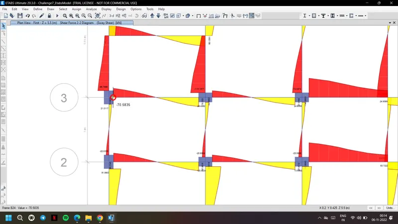
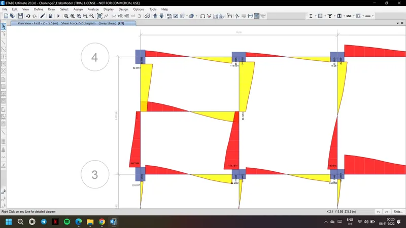
5. To get the maximum hogging and sagging moments of the beam go to concrete frame design and display design info, choose longitudinal reinforcement
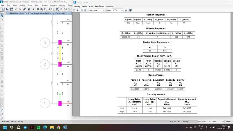
6. From that select the required beam, go to shear details and note down the capacity moments and equivalent shear force.
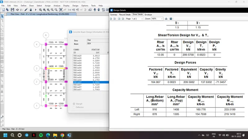
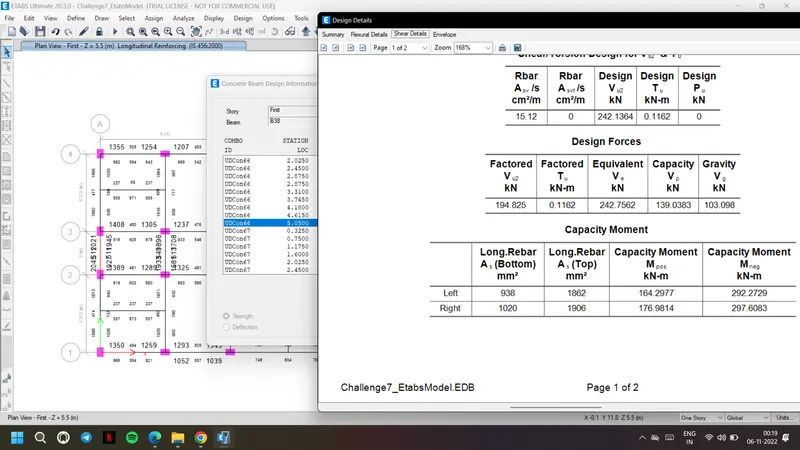
7. Now all the values are known calculate maximum shear force using the below given formula
8. After caluculation compare it with the equivalent design shear obtained from ETABS.
9. We can observe that for both the beams, equivalent design shear is greater than the applied maximum shear force at left and right ends of the beam
10. So the beams are safe in shear
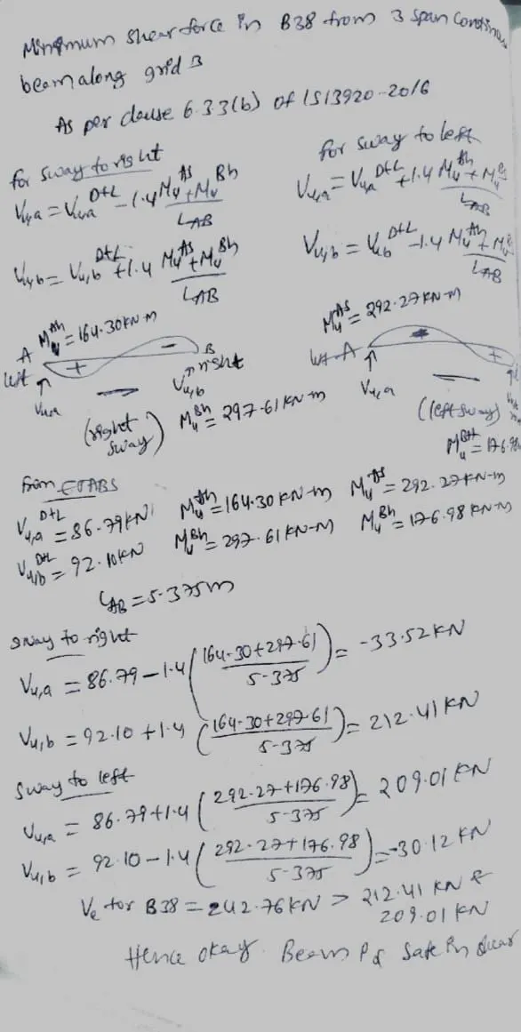
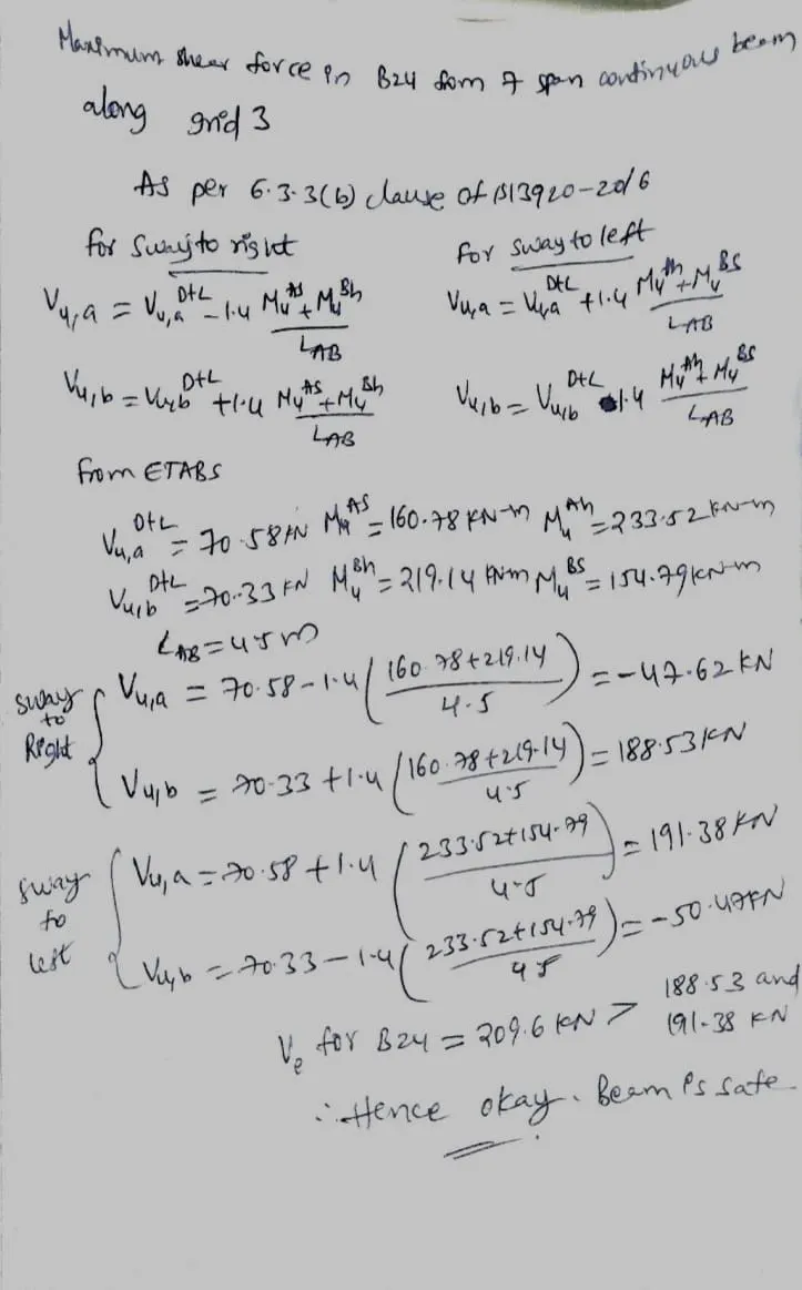
Result: Calculated value of the maximum shear force in one of the spans in both the continuous beams and compared them with the shear force calculated by ETABS. The design shear force calculated by ETABS is more than the maximum shear force acting on the spans, so the beams are safe.