Reinforcement Detailing of Beams from ETABS output
1.
Aim
To design the RCC moment resisting frames for the given G+4 building.
To provide the details of longitudinal and shear reinforcement for two continuous beams.
To provide reason for failure of middle span along grid A and possible ways of solution.
To calculate the maximum shear force in any one of the spans in both the continuous beams.
Reinforcement requirement as per code.
- Minimum reinforcement as per IS 13920 2016 Clause 6.2.1
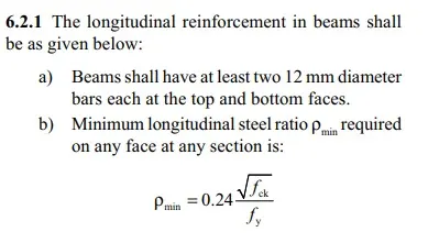
Fck is 25 N/mmSq and fy is 415 N/mmsq
Minimum longitudinal steel is = 360mm2
- Minimum shear reinforcement as per IS 456 Clause 26.5.1.6
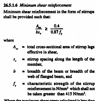
Considering the spacing as 1000mm and the breadth as 300mm, the Asv = 332 Sqmm
- Development length as per IS 456 Clause 26.2.1
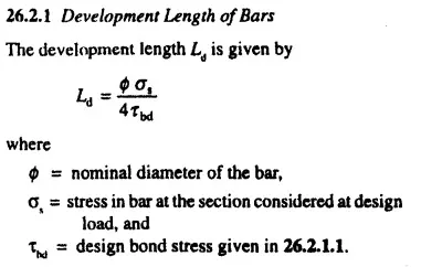
Design bond shear is 1.4 for M25, Stress is 230 N/mmsq
Development Length = 41 x Diameter of Bars.
Procedure
- Open the given ETABS file and the run the analysis.
- Then go to concrete frame design and run.
- Thus, the longitudinal reinforcement details are available.
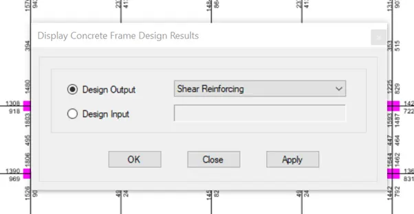
- Go to Display concrete frame details and change to shear reinforcement.
- Go to Concrete beam design Information and select the beam and we can see all the Longitudinal reinforcement and shear reinforcement details.
Outputs
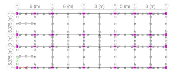
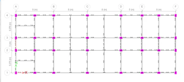
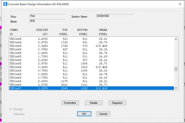
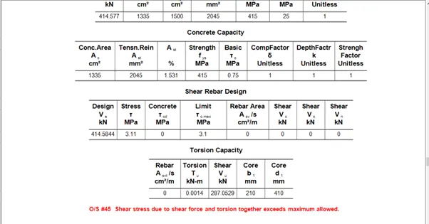
The failure of the beam is due to shear force and torsion together exceeds maximum allowed.
To avoid this shear failure, we know that stress is the ratio of load to area.
If we reduce the load acting on the beam then it will pass or we can increase the cross-section area of the beam to avoid the failure of beam.
The other possibility is to increase the shear capacity of the concrete by increasing the Grade of concrete from M25 to M30 for that particular beam.
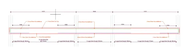
Reinforcement Details

Existing Shear Calculation
As per IS 456 2000 Claus 40.4
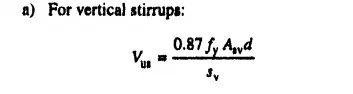
Fy = 415 N/mm2
Asv = 151mm2
D = 450mm
Sv = 100mm
Vu = 245kN