Reinforcement Detailing of Beams from ETABS output
AIM: -
Run the analysis and design the RCC Moment ResistingFrame.
Provide details of longitudinal and shear reinforcement for the two continuous beams.
Sketch the beam elevation details or draft it using autocad software.
Provide reasons for failure of the middle span along grid A. What are the possible ways this issue can be resolved?
Calculate value of the maximum shear force in any one of the spans in both the continuous beams, as per clause 6.3.3 (b) in IS 13920 – 2016.
Confirm these values from shear force demand calculated by ETABS.
PROCEDURE: -
Open the given file in ETABS
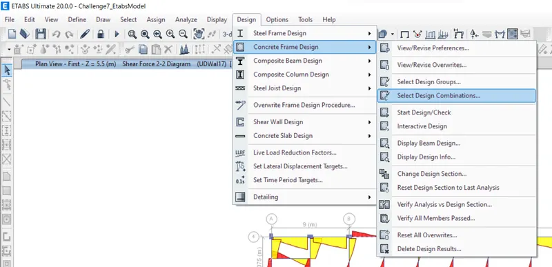
Click on DESIGN TAB
Click on Concrete Frame Design
Select Design Combinations
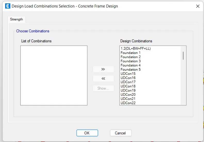
Design Load Combinations dialogue box opens
Choose the Combinations
Press OK
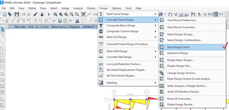
Click on DESIGN TAB
Click on Concrete Frame Design
Select Start/Design Check
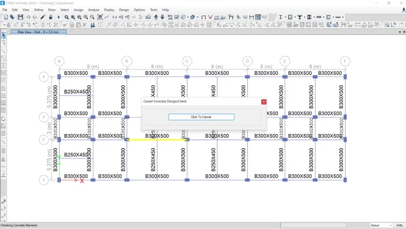
System designs the frame
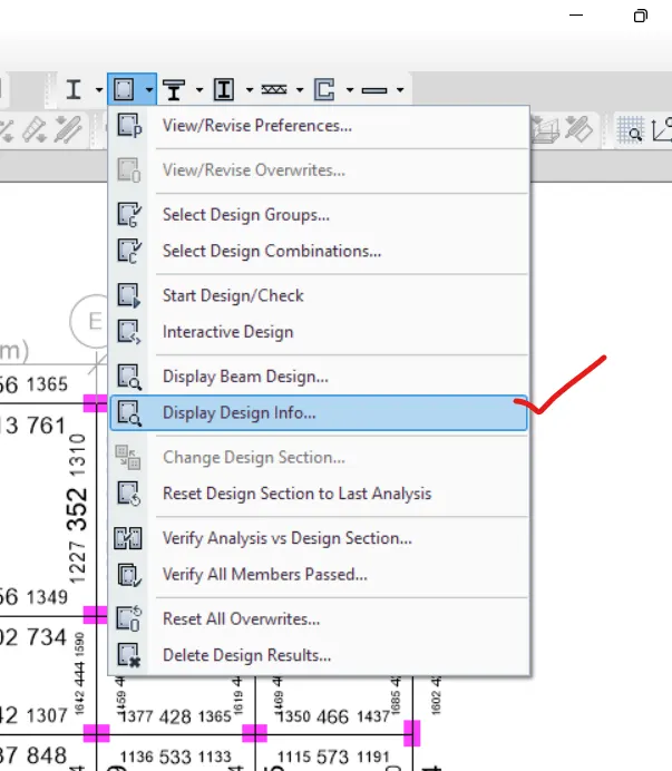
Click on DESIGN TAB
Click on Concrete Frame Design
Select Display Design Info
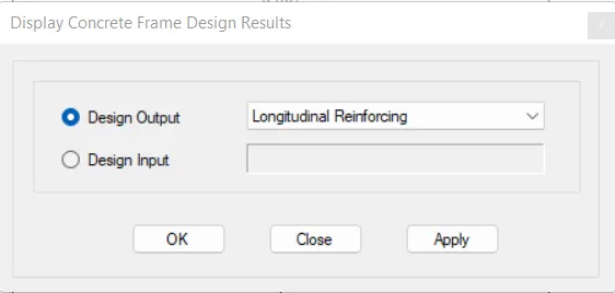
Display Concrete FrameDesign Results dialogue box opens
Design output: Longitudinal Reinforcing
Click on APPLY
Press OK
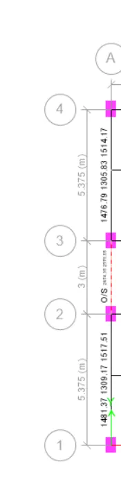
3 span constnuous beam along Grid A
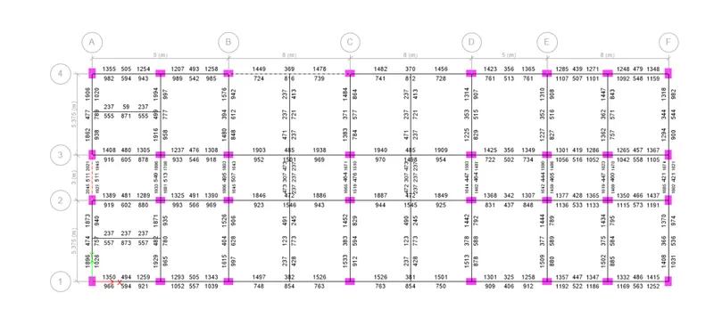
7 span continuous beam along grid 3

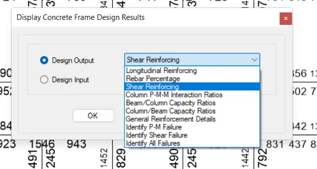
Display Concrete FrameDesign Results dialogue box opens
Design output: Shear Reinforcing
Click on APPLY
Press OK
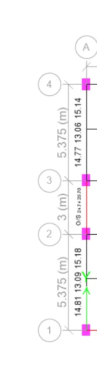
3 span constnuous beam along Grid A
7 span continuous beam along grid 3

- Reasons for failure of the middle span along grid A.
The mid span is failed because of over stress in the beam. The shear steel was not calculated for this beam,
Shear stress due to shear force and torsion together exceeds maximum allowed.
Design shear stress exceeds the shear capacity of the scetion.
- Possible ways to resolve this issue
Shear capacity varies with the grade of concrete.
Shear capacity depends on the size of the section.
Increase the Shear capacity of the section by increasing the size of the section or by increase the Grade of concrete of this beam alone.
As per IS 13920
Clause 6.1.1
width/depth>0.3 for Primary beams
`300/500 > 0.3`
0.6 > 0.3 …………………………O.K.
Clause 6.1.2
Width of beam (b)
b>200mm……………………….O.K.
Clause 6.1.3
Depth of beam < one fourth of span of beam
Depth of beam = 500mm <`(1/4)*8 =2m` ……….O.K.
LONGITUDINAL REINFORCEMENT
At Supports:
Clause 6.2.1
Pmin = `P_min=0.24 sqrt(fck)/(fy)`
`(A_(st))_min = 0.24*sqrt(25)/(500)*(300)*(445)`
Ast(min) = 386 mm2
Clause 6.2.2
`(A_(st))_max = 2.5/100 * 300 * 445`
Ast(max) = 3337.5mm2
Ast(min) < Ast(prov) < Ast(max)
386 < 1478 < 3337 mm2
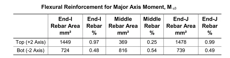
Provide 2 no's 25mm dia bars and 2 no's 20mm dia bars at Top
Clause 6.2.3
Ast(bottom) = ½ x 1478
= 739 mm2
`(A_(st))_(Bot= max [(A_(st))_(min),(1/2*A_(st))_(prov)]`
Provide 739 mm2
Provide 4 no's 16mm dia bars at bottom
At Centre:
Clause 6.2.4
At Top
`(A_(st))_(centre) >= ¼ *(A_(st))_(SUPPORT`
Ast(centre)>= ¼ *1482
>= 370.5 mm2………………O.K.
Provided 2 no's 16mm dia bars at Top
At Bottom
`(A_(st))_(centre) >= ¼ *(A_(st))_(SUPPORT`
Reinforcement provided at bottom span is 812 mm2
= `816 >= ¼ *1482`
= `816 >= 370.5 mm^2`………………O.K.
Provide 2 no's 20mm dia bars at bottom
Provide 2 no's 12mm dia bars at bottom
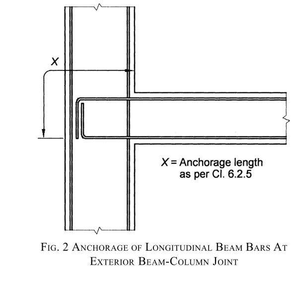
Clause 6.2.5
Anchorage Length
`L_d = (0.87*fy*d)/(4tau_(bd))`
= `(0.87*415*d)/(4*(1.6)*1.4)`
= 40d
Anchorage Length = Ld +10d -8d
(Allowance for 90 degree bend = 8d)
X =42d
X =42*32
X =1344mm
TRANSVERSE REINFORCEMENT
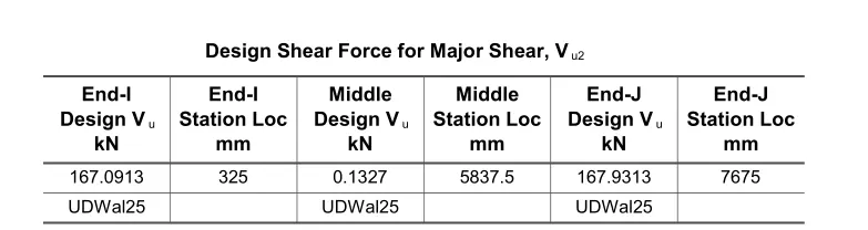
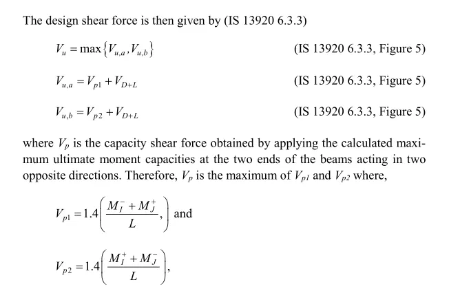
`V_(u2)`= Factored shear force from load combinations.
`V_(e)` = Sway or Seismic Shear force
`V_(e)= V_p+V_g`
Design Shear force= max(`V_(u2),V_e`)
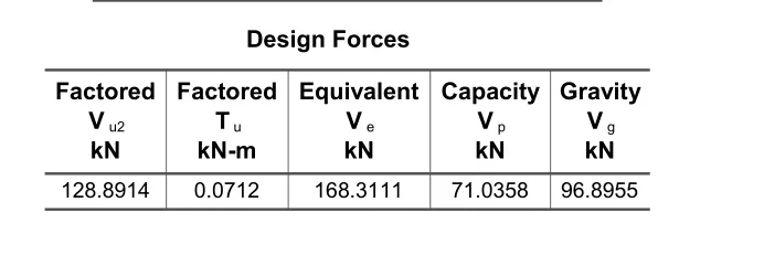
Design Shear force Vu = 168.31 kN
Clause 6.3.5
Close Spacing of Links:
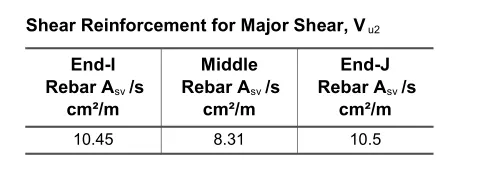
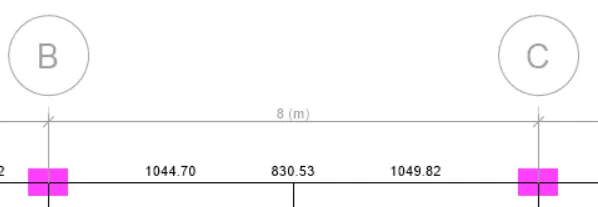
Shear Reinforcement at supports = 1050mm2
Shear Reinforcement at centre = 831 mm2
Provide 2 legged 10mm bar as stirrups
No of stirrups = `1050/(2*pi/4*10^2`
No of stirrups = 7
Spacing at Supports:
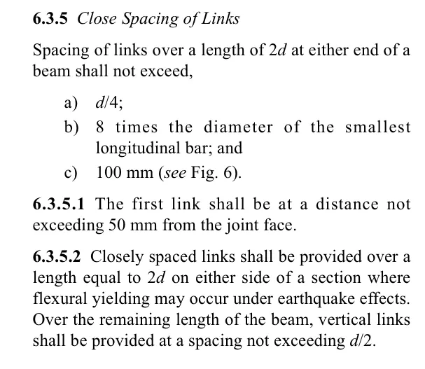
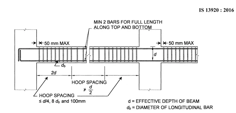
a) d/4 = 445/4
= 115mm
b) 8*16 = 128mm
c)100mm
c) 2*445 = 890mm
890-50 = 840mm
(7*10)+(6*Sv)=840
Sv=128mm
Provide 125mm spacing
Spacing at Centre:
spacing <d/2
<445/2
<222mm
Provide 220mm spacing at centre.
Calculated Shear Force demand as per IS 13920-2016

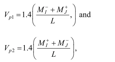
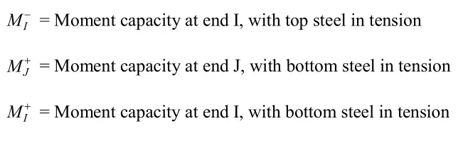

`V_(D+L)`= Contribution of factored shear force from the in-span distribution of gravity loads
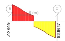
`V_(u,a)^(D+L)` = 92.99 kN
`V_(u,b)^(D+L)` = 93.8647
Ast at joint i @ top = 1608.5 mm2
Ast at joint i @ bottom = 942 mm2
Ast at joint j @ top = 1608.5 mm2
Ast at joint j @ bottom = 942 mm2
`M_i^(-)= 0.87*f_y*A_(st)(d-0.42*x_u)`
`M_i^(-)= 0.87*415*1608.5(445-0.42*(0.87*415*1608.5)/(0.34*25*300))`
`M_i^(-)` = 205kN-m
`M_j^(+)= 0.87*415*942(445-0.42*(0.87*415*942)/(0.34*25*300))`
`M_j^(+)` = 133.35 kN-m
L= 7.675m
Sway shear force to Right
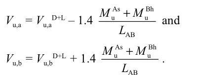
`M_(as)` = 133.35 kN-m
`M_(bh)` = 205 kN-m
`V_(d+l)`= 93 kN
L = 7.675m
`V_(u,a)`= 31.28 kN
`V_(u,b)`= 154 kN
Sway shear force to Left
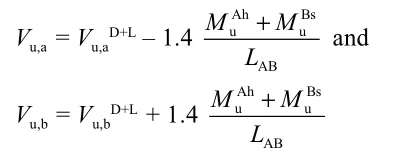
`M_(as)` = 205 kN-m
`M_(bh)` = 133.35 kN-m
`V_(d+l)`= 93.86 kN
L = 7.675m
`V_(u,a)`= 154 kN
`V_(u,b)`= 31.28 kN
Existing Shear Capacity in Beam as per IS 456 Clause 40.4
`V_(us) = (0.87*f_y*A_(sv)*d)/s_v`
fy = 415 N/mm2
Sv = 125mm
d = 445mm
Asv = 156 mm2
`V_(us)`= 200kN
Hence Shear Rebar in drawing as per 13920-2016 code guideline is OKAY
RESULT: -
We ran the analysis and designed the RCC Moment ResistingFrame.
Provided details of longitudinal and shear reinforcement for the two continuous beams.
Sketched the beam elevation details or draft it using autocad software.
Provided reasons for failure of the middle span along grid A and the possible ways this issue can be resolved.
Calculated value of the maximum shear force in any one of the spans, as per clause 6.3.3 (b) in IS 13920 – 2016.
Confirmed these values from shear force demand calculated by ETABS.
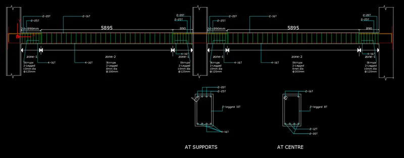
TRANSVERSE SHEAR REINFORCEMENT: -
3 span constnuous beam along Grid A 7 span continuous beam along grid 3
LONGITUDINAL FLEXURE REINFORCEMENT: -
3 span constnuous beam along Grid A 7 span continuous beam along grid 3