Reinforcement Detailing of Beams from ETABS output
Detail design of beams in Etabs 2018.
The ETABS file for a G+4 building is provided. Run the analysis and design the RCC Moment ResistingFrame. The following challenge deals specifically with two continuous beams in the 1st floor.
1) 3 span continuous beam along grid A
2) 7 span continuous beam along grid 3
Address the following issues thereafter.
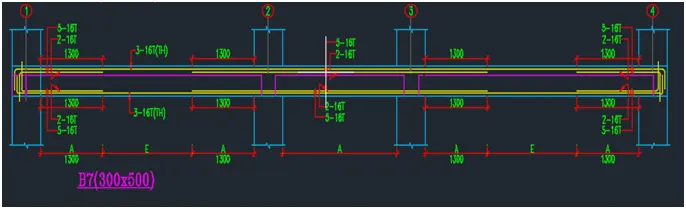
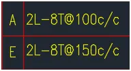
• Provide details of longitudinal and shear reinforcement for the two continuous beams. Sketch the beam elevation details or draft it using autocad software. A sample of how beam elevation details is prepared in consultancy firms is provided below. Participants can prepare it as per their preference:
• Provide reasons for failure of the middle span along grid A. What are the possible ways this issue can be resolved?
• Calculate value of the maximum shear force in any one of the spans in both the continuous beams, as per clause 6.3.3 (b) in IS 13920 – 2016. Also, confirm these values from shear force demand calculated by ETABS.Please note that if longitudinal reinforcement provided is more than required (as per ETABS results), the shear force demand will vary from what is provided by ETABS.
Ans:-
Aim:- To find out the area of steel and provide the shear reinforcement for the given selected beams by using ETABS.
Procedure:-
- Run the analysis for given plan
- Select concrete frame design button we can see longitudinal reinforcement details for the selected floor.
- Record the data by taking screenshot of required beam
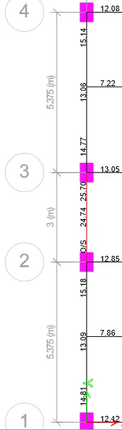
- Concrete frame design-display design info- change longitudinal into shear reinforcement.(generally longitudinal values are in 1000's where as shear are in 10's)
- We can differentiate the values of their placements like left top and bottom right top and bottom and middle top and bottom.
- We can check the details of the beam by right click on it.
- We may found rebar area in cm^2/m so we must convert it into mm^2/m (Record the detail by taking screenshot)
- Beam along Grid-A span got failed. due to o/s (over stressed which is impossible to calculate)
- Right click on it - details- shear details-at bottom we can see the o/s notification.
- conclusion: shear capacity of the concrete varies with it's grade.(so we can provide higher grade to that beam which is o/s)
- We have to increase and decrease the loadings.
- Additional reinforement guideline from IS:13920-2016 (clause6)
- As per IS:13920-2016 clause 6.3.3(b)


| Sway shear force to right | Sway shear force to left |
|
Vu,a = Vu,a^D+L - 1.4 ((Mu^AS + Mu^Bh) /Lab) |
Vu,a = Vu,a^D+L - 1.4 ((Mu^Ah + Mu^Bs) /Lab) |
| Vu,b = Vu,b^D+L - 1.4 ((Mu^AS + Mu^Bh) /Lab) | Vu,b = Vu,b^D+L - 1.4 ((Mu^Ah + Mu^Bs) /Lab) |
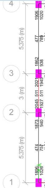
| Mas = 174 knm | Mah = 234 knm |
| Mbh = 293knm | Mbs = 155knm |
| Lab = 4.725m | Lab = 4.725m |
| Vd+1 = 92kn | Vd+1 = 70kn |
| Vu,a = 46kn | Vu,a = 185kn |
| Vu,b = 230kn | Vu,b = 45kn |
The above all results we get from ETABS envelope
Vu,a^D+L, Vu,b^D+L to get these we need to add sway of 1.2 inn load combinations.
Provided reinforcement must satisify the sway shear requirement.
shear>sway
Existing shear capcity in beam as per drawing
(As per IS:456-2000 clause 40.4)
Vus = 0.87fy Asv d / Sv
Fy = 415 N/mm^2
Asv = 151mm^2
d=450mm
Sv=100mm
Vus=245kn
Hence shear rebar in drawing is okay as per IS:13920 code guidelines
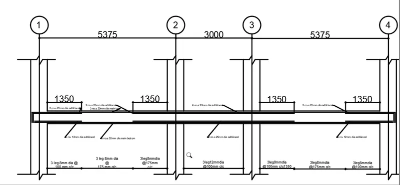
Result:- Finally i got to know how to provide shear reinforcement and longitdinal reinforcement for a beam by using ETABS software.