Reinforcement Detailing of Beams from ETABS output
Detailed design of beams in ETABS 2018.
The ETABS file for a G+4 building is provided. Run the analysis and design of the RCC Moment Resisting Frame. The following challenge deals specifically with two continuous beams on the 1st floor.
a) 3 span continuous beam along grid A
b) 7 span continuous beam along grid 3
Address the following issues thereafter.
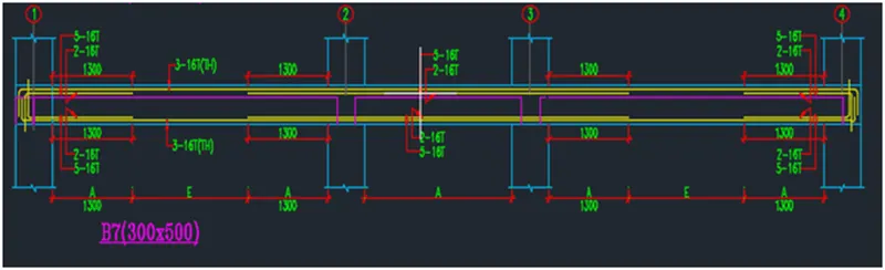
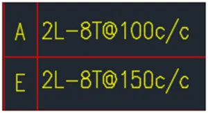
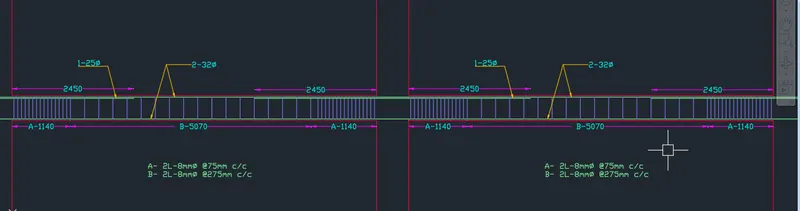
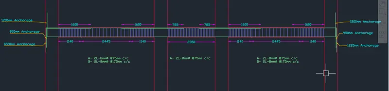
• Provide details of longitudinal and shear reinforcement for the two continuous beams. Sketch the beam elevation details or draft it using AutoCAD software. A sample of how beam elevation details are prepared in consultancy firms is provided below. Participants can prepare it as per their preference:
• Provide reasons for the failure of the middle span along grid A. What are the possible ways this issue can be resolved?
• Calculate the value of the maximum shear force in any one of the spans in both the continuous beams, as per clause 6.3.3 (b) in IS 13920 – 2016. Also, confirm these values from the shear force demand calculated by ETABS. Please note that if longitudinal reinforcement provided is more than required (as per ETABS results), the shear force demand will vary from what is provided by ETABS.
AIM
To provide reinforcement Details of the continuous beams on grid A and grid 3.
PROCEDURE
Open the provided ETABS model
Analyse > Check model
Analyse > Run Analysis
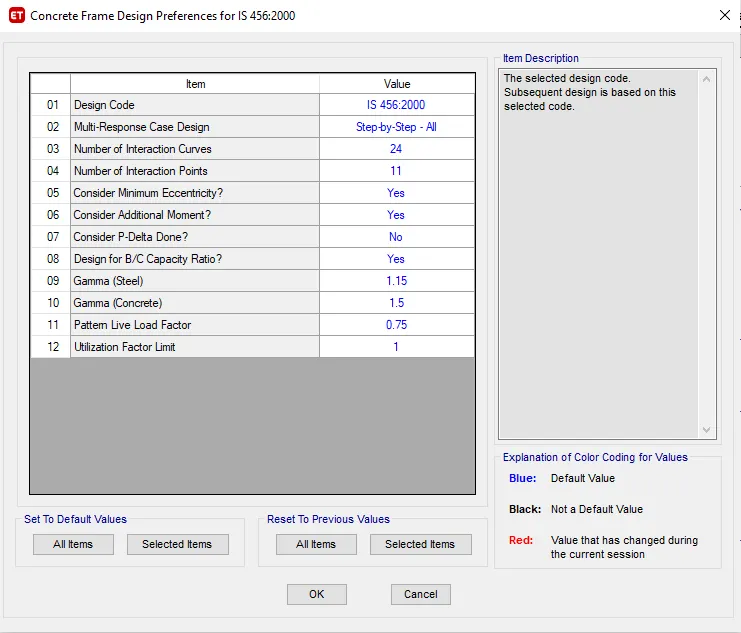
Design > Concrete Frame design> View/Revise Preference
Design > Start design/check
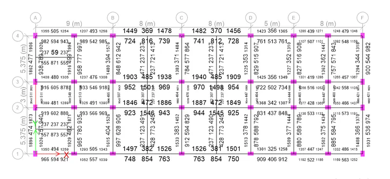
The provided ETABS model is analysed and designed as per IS 456:2000 in ETABS as shown below.
Design > Verify all members passed
Design > Display design info > Longitudinal reinforcing
Design > Display design info > Shear reinforcing
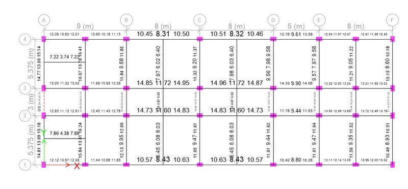
Once the analysis is complete the detailing of the beams in grid A and grid 3 is drawn as shown below according to the steel provided.
The detailed beams are as follows.
Seven-Span Continuous Beam along Grid-3
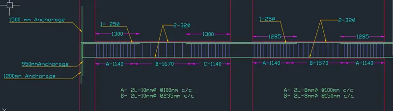
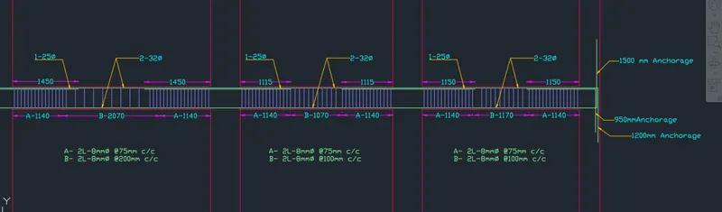
Three-Span Continuous Beam along Grid-A
The scope of failure in midspan of Grid-A RC beam:
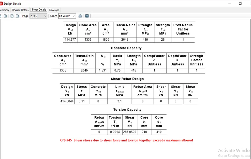
The central span of the Grid-A RC beam has failed due to high shear stress. As per the above shear force value (3.11 MPa) against the maximum allowable shear stress (3.1 MPa), is almost failing but passes numerically. This design shear force has arrived in the philosophy of the Capacity design concept. This can be resolved by following any of the mentioned options:
- Optimizing provided flexural reinforcement
- Reducing the depth of the RC beam which in turn reduces stiffness and flexure requirement
- Increasing concrete grade will increase the allowable shear stress limit.
Calculation of Design shear force of RC beams complying clause 6.3.3 (b) of IS 13920-2016:
As per clause 6.3.3, the shear reinforcement provided in the beam must be able to take up the maximum sway shear induced for the same section. At the same time, part (b) of clause 6.3.3 also mentions the formula to obtain the sway shear in both directions that are left and right which is given as follows:
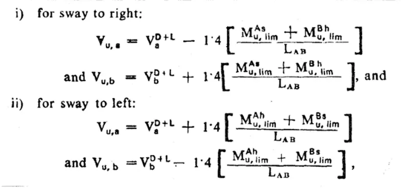
So, using the above formula, we will calculate the sway shear as given below:
First, we need to calculate the shear force at supports due to the factored gravity loads to arrive at the values for Va(D+L) and Vb(D+L). So, we add a new load combination with dead and live gravity loads with the safety factor 1.2 mentioned in the IS code.
- Check for Sway to the Right
Below are the given values from the ETABS model:
`V_u^(D+L)= 92kN`
`M_u^(As)=174kN`
`M_u^(Bh)=293kN`
`L_(ab)=4.725m`
Now we can insert the relevant values and obtain the sway shear values as follows:
`V_(u, a)= V_( a)^(D+L)-1.4frac{M_u^(As)+M_u^(Bh)}{L_(ab)}`
`V_(u, a)= 92-1.4frac{174+293}{4.725}`
`V_(u, a)= 48kN`
`V_(u, b)= V_( b)^(D+L)+1.4frac{M_u^(As)+M_u^(Bh)}{L_(ab)}`
`V_(u, b)= 92+1.4frac{174+293}{4.725}`
`V_(u, b)= 231kN`
- Check for Sway to the Left
Below are the given values from the ETABS model:
`V_u^(D+L)= 74kN`
`M_u^(As)=236kN`
`M_u^(Bh)=150kN`
`L_(ab)=4.725m`
Now we can insert the relevant values and obtain the sway shear values as follows:
`V_(u, a)= V_( a)^(D+L)+1.4frac{M_u^(As)+M_u^(Bh)}{L_(ab)}`
`V_(u, a)= 74+1.4frac{236+150}{4.725}`
`V_(u, a)= 189kN`
`V_(u, b)= V_( b)^(D+L)-1.4frac{M_u^(As)+M_u^(Bh)}{L_(ab)}`
`V_(u, b)= 74-1.4frac{236+150}{4.725}`
`V_(u, b)= 40kN`
So, the maximum shear among the four values is 231 kN. Therefore, the stirrups designed for this beam must be able to resist more than 231kN of shear force for a safe beam design. Thus, let's check how much our stirrups can take in terms of the shear force.
Existing Shear Capacity in beam:
Calculating the existing shear capacity in the beam as per IS 456-2000:
`V_(us)=(0.87f_yA_(sv)d)/S_v`
fy = 415 N/sq.m.
Asv = 151 sq.m.
Spacing = 150 mm.
d = 450 mm.
`V_(us)=(0.87*415*151*450)/150`
`V_(us)=245 kN`
Hence the Shear capacity which is 245 kN is larger than the Shear sway which is 230 kN. So it means that it is safe.