Radar Mast & Final Assembly of Yacht
OBJECTIVE:
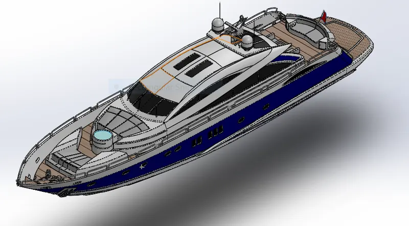
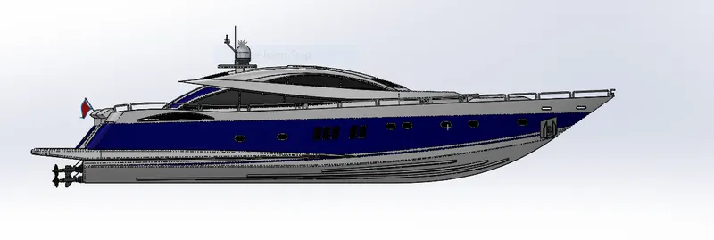
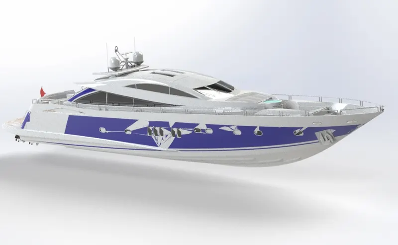
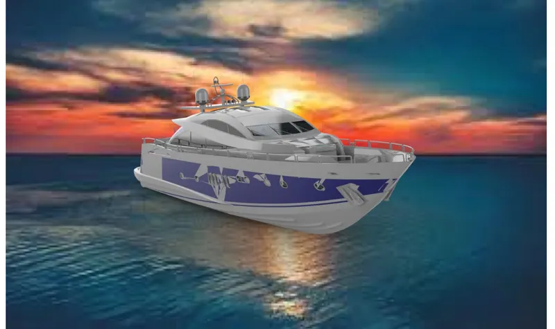
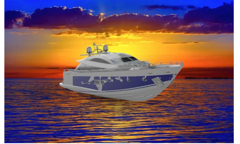
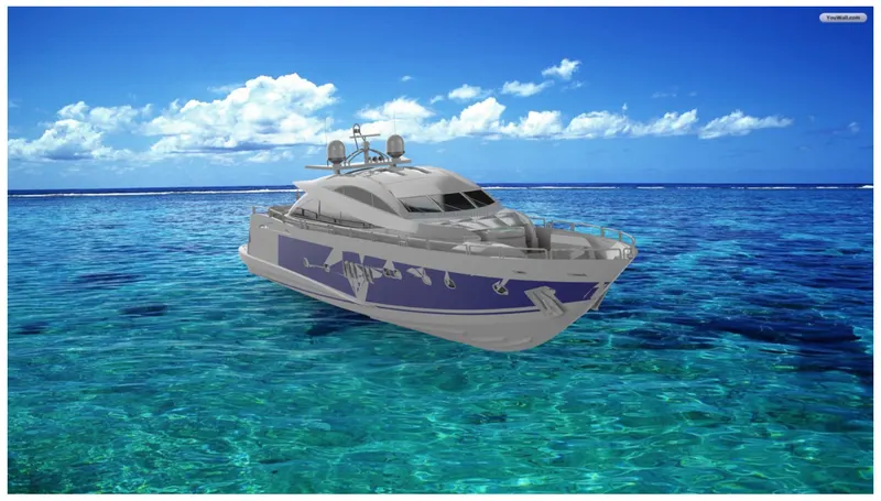
The objective of the project is to design and model all the parts of an Sunseeker Predator Yacht and assembling it to create the Photo-Realistic rendering of the yacht.
INTRODUCTION:
In this project the SUNSEEKER Predator Yacht was taken as a conceptual model, to understand the 3D modeling methodology of Solid modeling and Surface modeling. Each and every, part of the yacht was designed and modeled using SOLID WORKS.
DESIGN METHODOLOGY:
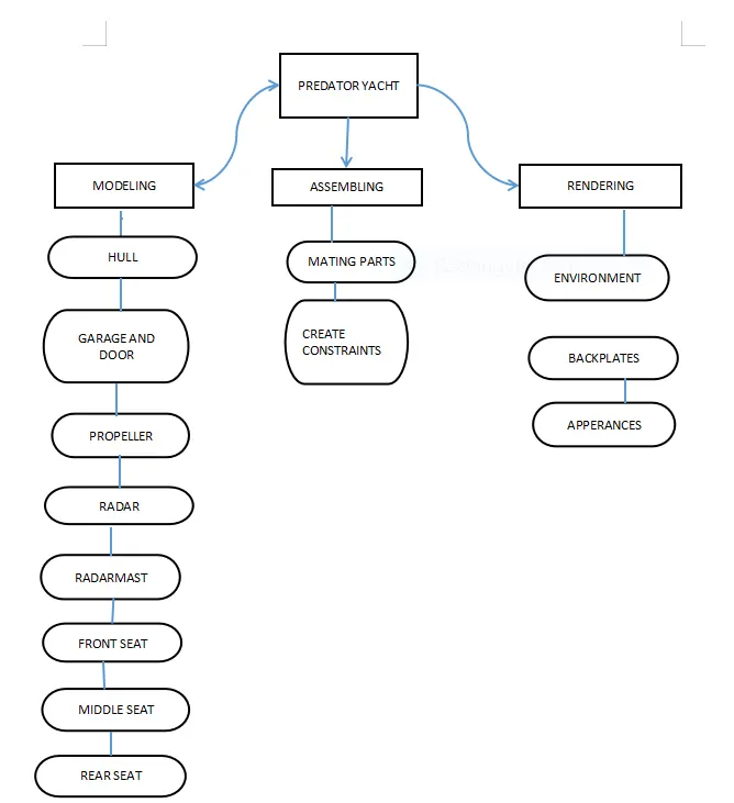
FEATURES, COMMANDS AND TOOLS:
Sketch - Create the sketches and decide how to dimension and where to apply relations.
Features - Select the appropriate features, such as extrudes and fillets, determine the best features to apply, and in what order to apply those
features must be decided.
Surfaces - Surfaces are tools for geometry that can be used to create solid features.
Assembly - Select the components to mate and the types of mates to apply.
Smart Dimension - Creates a dimension for a selected sketch entity.
Line - Line is used to draw horizontal, vertical or inclined line.
Circle - The circle is another important sketching tool which enables to create the circular drawing on the graphics area.
Rectangle - Sketches rectangles or square with a center point at a selected angle. Parallelogram sketches a standard parallelogram.
Spline - A two- or three-dimensional curve defined by a set of control points. Points within a spline can be added or deleted.
Ellipse - Sketches a complete ellipse.
Tangent Arc - An incomplete circle defined by its tangency to the sketch entity.
Sketch Fillet - A tangent arc in between two sketch entities can be created
Offset Entities - Copy a sketch entity to a specific distance from the original entity. Must have a sketch entity already drawn and selected to use the tool.
Sketch Picture - Insert an image file into the background nd of a sketch. This allows the user to 2D sketches based oft of the image. Use the sketch picture re property manager to alter the inserted image.
Mirror Entities - Create a reflected copy of a desired entity about a centerline or axis.
Move Entities - Dimensions are moved or copied to the new location with the entities. Relations are moved or copied only if we select Keep relations.
Linear Sketch Pattern - Pattern a sketch entity either horizontally, vertically, or angled.
Circular pattern tool: It can be found under the drop-down arrow. It performs similarly to the linear sketch pattern except that it requires the user to specify a point to revolve about and a radius.
Convert Entities - Convert Entities enables you to copy model edges into your active sketch. These sketch elements are automatically fully defined and constrained with an On Edge relation. Convert Entities is like Offset Entities except that the offset distance is always zero.
Intersection Curve - Tool Intersection Curve opens a sketch and creates a sketched curve at the following kinds of intersections.
Trim Entities - Sketch entities can be trimmed shorter using the Trim Entities tool.
Extend Entities - You can add to the length of a sketch entity line, centerline, or arc. Use Extend Entities to extend a sketch entity to meet another sketch entity.
Sketch Contours - Sketch Contours al ow you to select portions of a sketch that are generated by the intersect ion of geometry and create features.
Extruded Boss - One of the oldest com mand s in the SOLIDWORKS software is the boss/base extrude command. An Extruded Boss/Base feature re will allow us to take a 2D sketch and add thickness to it in the third dimension.
Extruded Cut - I t's a tool to remove material by projecting a sketched section normal to the sketching plane.
Curve Driven Pattern - The Curve Driven Pattern tool allows us to create patterns along a planar or 30 curves. To define the pattern, we can use any" Sketch Driven
Pattern - The sketch driven pattern creates copies of existing features and places them wherever we've added a point in a sketch.
Revolved Features - Material can be added or removed from a model by using the Revolve command. Revolves add or remove material by revolving one or more profiles around a centerline. We can create revolved boss/bases, revolved cuts, or revolved surfaces. The revolve feature can be a solid, a thin feature, or a surface. Revolved featured are created by rotating a sketch around a centerline. The centerline becomes the axis of revolution.
Fillets - Filleting refers to both fillets and rounds. The distinction is made by the geometric conditions.
Chamfer: tool creates beveled faces. A chamfer, like a fillet, is an applied feature. And does not require you to make a sketch to create the feature.
Section View - Section View cuts the view using one or more section planes. The planes can be dragged dynamical y. Reference planes or planar faces can be used. To check our work and see how the parts fit together, we can use the section view.
Mirror - Features can be mirrored about a plane or planar face. The mirrored features maintain a relationship with the original features such that any changes to the original features are also made on the mirrored features.
Split - Lines are used to divide model faces into two. Split lines are created like any other sketched feature. They can be one or more connected sketch entities. They must be oriented so that they will pass through model faces when projected normal to the sketch plane.
Combine - In a multi body part. we can combine multiple bodies to create a single body.
Sweeps - Sweeps take a sketch, called a Profile and move it along a Path. It must be a closed, non-self-intersecting boundary. However, the sketch can contain multiple contours - either nested or disjoint.
Lofts - Lofts create a solid by connecting a series of loft profiles. These profiles can be different shapes. Lofted Boss/Base adds material between
Pierce - The Pierce relationship is used in sweeps. It can be thought of as a 3D Coincident relationship.
Reference Geometry - Reference geometry defines the shape or form of a surface or a solid. Reference geometry includes items such as planes
Project Curve - Select Bi-directional to create a projection that extends on both sides of the sketch. The curve can be used as a path for a sweep.
Composite Curve - We can create composite curves by combining curves, sketch geometry, and model edges into a single curve. Composite curve can be used as a guide curve when creating aloft or a sweep.
Split Line - The Split Line tool is used to project an entity (sketch, solid, surface, face, plane, or surface spline) onto other surf aces or curved/planar faces. We are also able to split faces on multiple bodies with one command."
SURFACE COMMANDS
Lofted Surfaces — Creates a lofted surface between two or more profiles or sketches. Specify start and end constraints and add guide curves
Boundary Surfaces —The boundary surface feature lets us to create surfaces that can be tangent or curve continuous in both directions (all sides of the surface). In most cases, this delivers a higher quality result than the loft tool.
Extruded Surfaces — Extrudes a sketch or selected sketch contours in one or two directions two create a surface features
Revolved Surfaces — Revolves a sketch or selected sketch contours around and create a surface feature.
swept Surfaces — lt Sweeps a dosed profile along an open or closed path to create a surface feature. It uses a tangent plane at the end of the path so that the path is normal to the swept surface.
Filled Surfaces — Patches a surface within a boundary defined by edges, sketches, or curves. We can use constraint curves to fill surfaces and adjust resolution control to improve surface finish.
Ruled Surfaces— Inserts ruled surfaces in a specified direction from edges. Tangent to surface, Normal to surface, tapered to vector, perpendicular to vector or sweep can be selected. We can also trim and knit the surfaces and remove any connecting surfaces.
Trim Surface — It trims the surfaces where a surface intersect with another surface. a plane or a sketch
Knit Surface— It combines two or more adjacent, non-intersecting surfaces into a single surface body. The surfaces must joint at an edge. If the resulting knit surface encloses a volume, we can create a solid body from the Properly Manager
Move Copy surfaces— Moves or copy surfaces about a plane or a sketch.
Offset Surface — Offset surfaces using one or more contiguous faces. This tool helps us to create an offset surface with gaps.
Extend Surface — Extends one or more edges or faces on a surface, based on end conditions and extension type.
Offset Surface — Offsets surfaces using one or more contiguous faces. This tool helps us to create an offset surface With gaps.
Extend Surface — Extends one or more edges or faces on a surface, based on end conditions and extension type.
Mirror surfaces —A Mirror surface creates a copy of a selected feature, mirrored about a plane or planar face. A mirror sketch entity is a copy of a selected sketch entity that is mirrored about a center line. If the original feature or sketch is modified, the mirrored copy is updated to ,effect the change.
Reference plane — We can create planes in part or assembly documents. We can use planes to sketch, to create a section view of a model, for a neutral plane in a draft feature, and so on.
Projected curve —A projected curve is typically used either in sweeps and lofts as path or guide curve.
Split line —The Split Line tool projects an entity (sketch, solid, surface, face, plane, or surface spline) .We can split curves on multiple bodies with one command.
Split point — We can split a sketch entity to create two sketch entities.
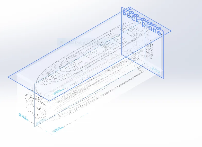
BLUEPRINT SETUP:
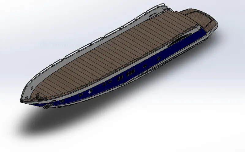
HULL:
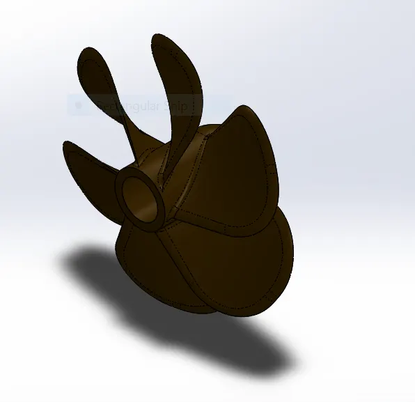
PROPELLER:
RADAR:
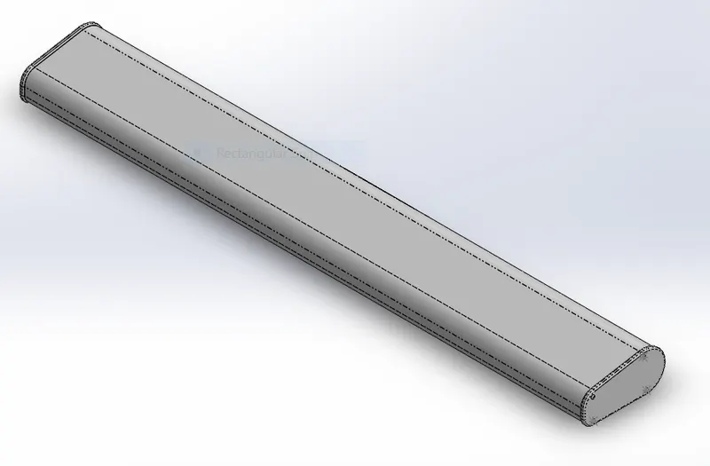
GARAGE AND DOOR:
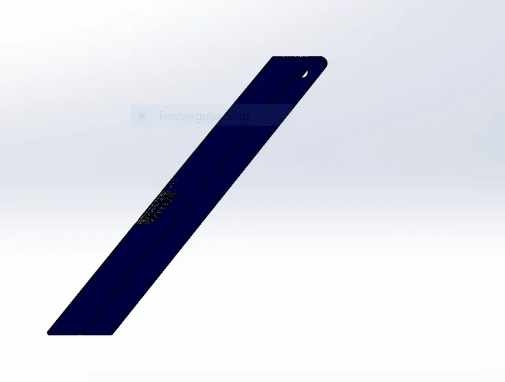
FRONT SEAT:
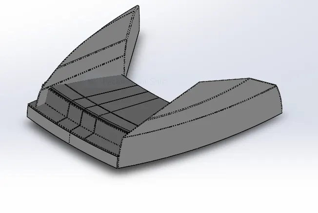
MIDDLE SEAT:
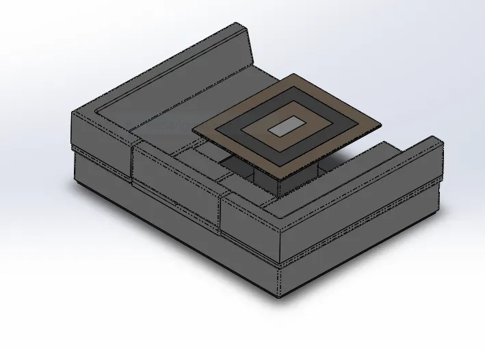
REAR SEAT:
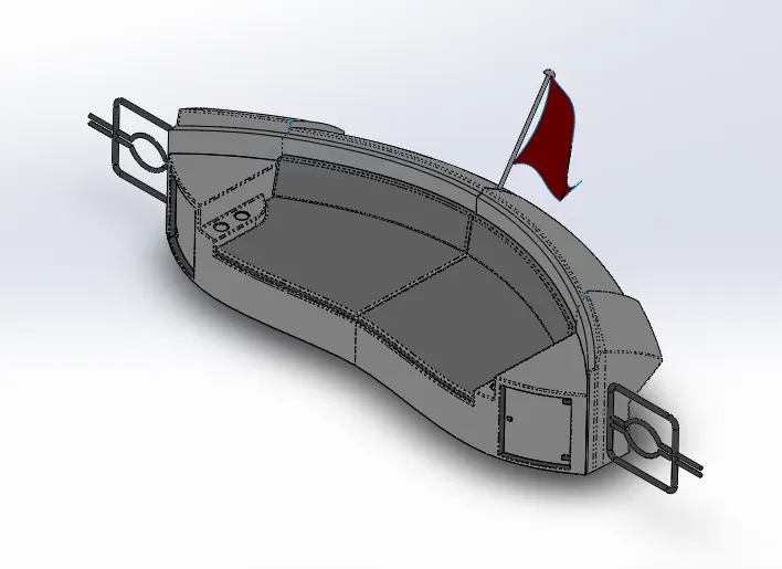
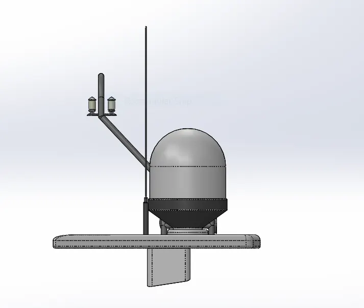
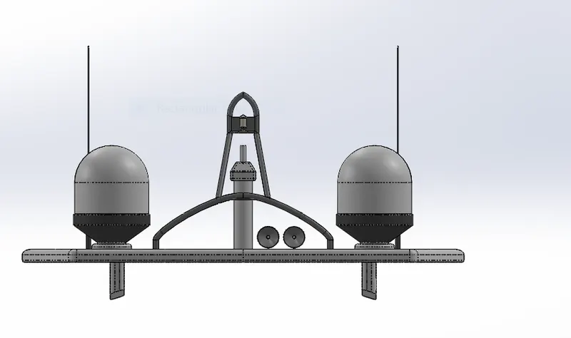
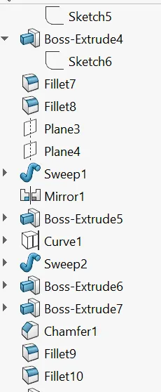
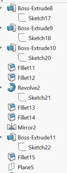
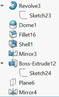
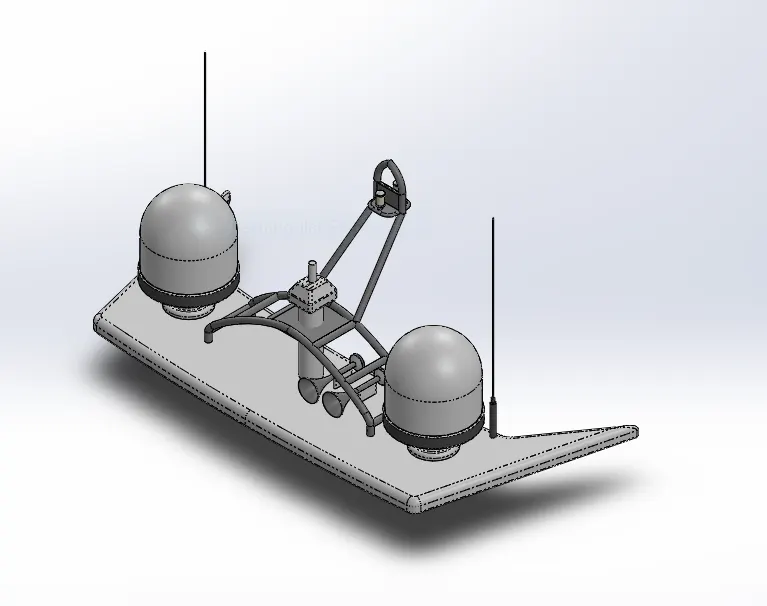
RADAR MAST:
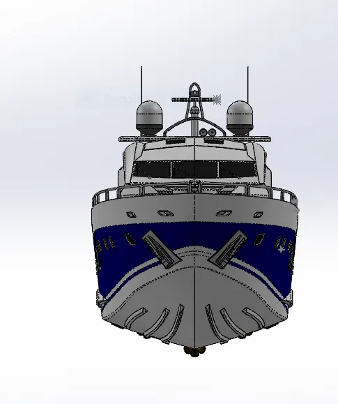
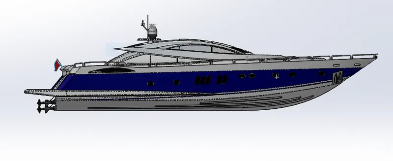
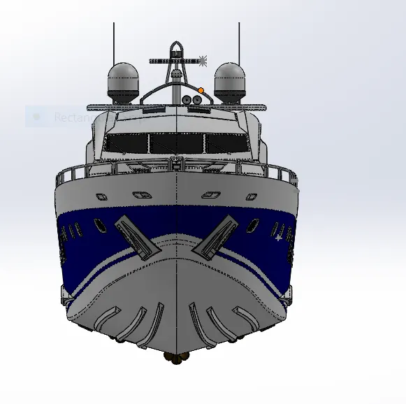
FRONT,ISOMETRIC AND LEFT VIEW OF ASSEMBLY YATCH:
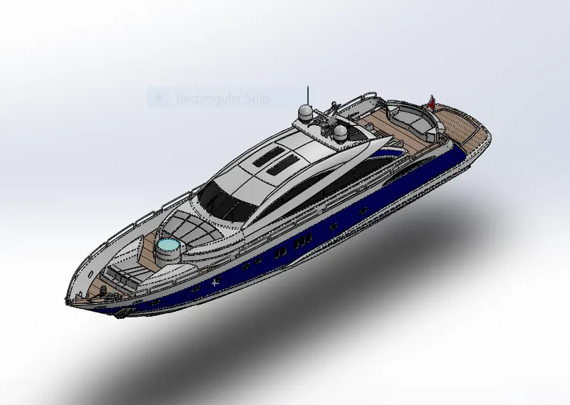
RENDERING IMAGES:
CONCLUSION:
Thus the project Design and Assembly of SUNSEEKER PREDATOR YACHT with photo realistic rendering using SOLiDWORKS has been created and completed successfully.