Advanced Sheet Metal Design Using NX Cad Challenge_1_Casing Design
OBJECTIVE:
The main objective of this project is to design a sheet metal casing in NX cad sheet metal application workbench. Also to perform the drafting for the casing part.
INTRODUCTION:
The sheetmetal application provides an environment for the design of sheet metal parts used in Machinery, Automotive and Aerospace. Enclosures, Brackets and other parts are normally manufactured with break press. The sheet metal application are widely used in the
- Aircraft Bodies
- Automobiles
- Utensils used for domestic purpose
- Beverage cans
In sheetmatal application we can create a uniform thickeness sheetmetal parts using basic features such as flange, tabs and jogs. We can also do close corners, cutout and stiffening features. The complex sheet metal part can be desinged in the solid model workbench and then we can convert it into a sheet metal part. We can also import, clean up and convert a non sheet metal part into a valid sheet metal part. Flat pattern sheet metal data can be used for the manufacturing process. The Material parameters such as thickness, bend radii and bend relief can be easliy set as default settings.
DESIGN METHODOLOGY:
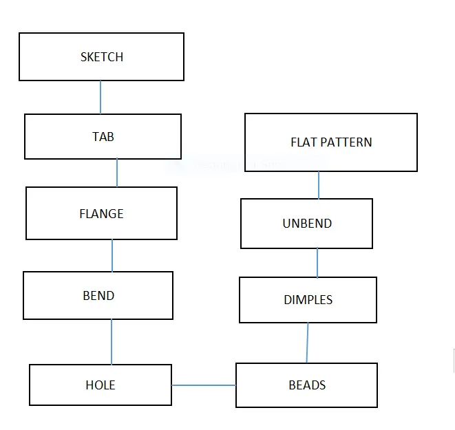
DESCRIPTION:
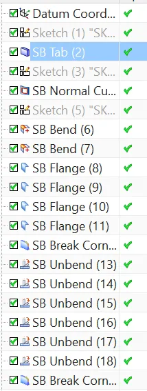
Tab: This command is used to create the base feature by extruding the sketch along a vector by a thickness value.
Normal cutout: This command is used to cut the material by projecting the sketch onto the model and then cutting perpendicular to the faces intersected by the projection.
Flange: This command is used to add a flat flange at an angle to the planar face and add a bend between the two.
Break Corner: This command is used to round or chamfers sharp corner of a tab or flange.
Unbend: This command is used to unbend the sheet metal. The punching operation can be performed only by unbending the sheet metal.
Dimple: This command is used to create a raised dimple feature in the sheet metal part. The dimple can be placed on any flat face including flanges and will extend in the direction of the faces.
Bead: This command is used to create a long drawn out impression, which is imoressed to increase the stiffeness in the sheet metal part. Mirror option is used to mirror the feature.
Falt Pattern: This is used to create a atomatically flattened version of sheet metal parts and prepare the model for manufacturing process. This flat pattern remains the last feature in the model tree.
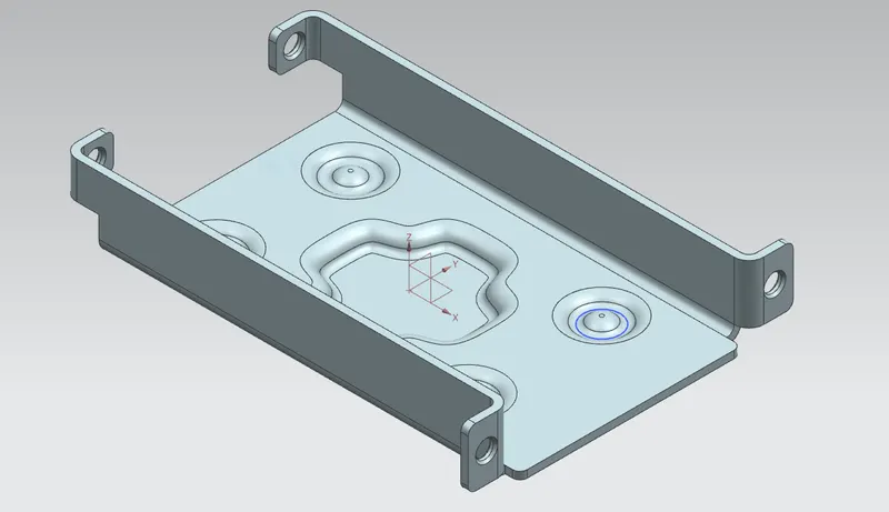
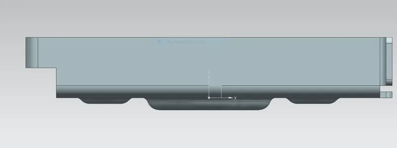
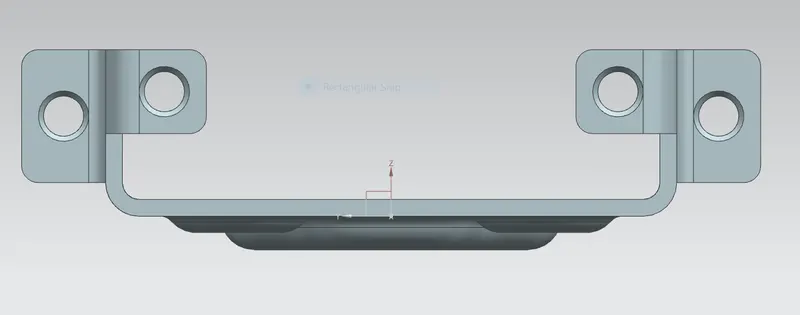
FRONT,SIDE AND ISOMETRIC VIEWS:
CONCLUSION:
Thus the sheet metal Casing part is designed and drafted sucessfully in NX cad sheet metal application workbench.